

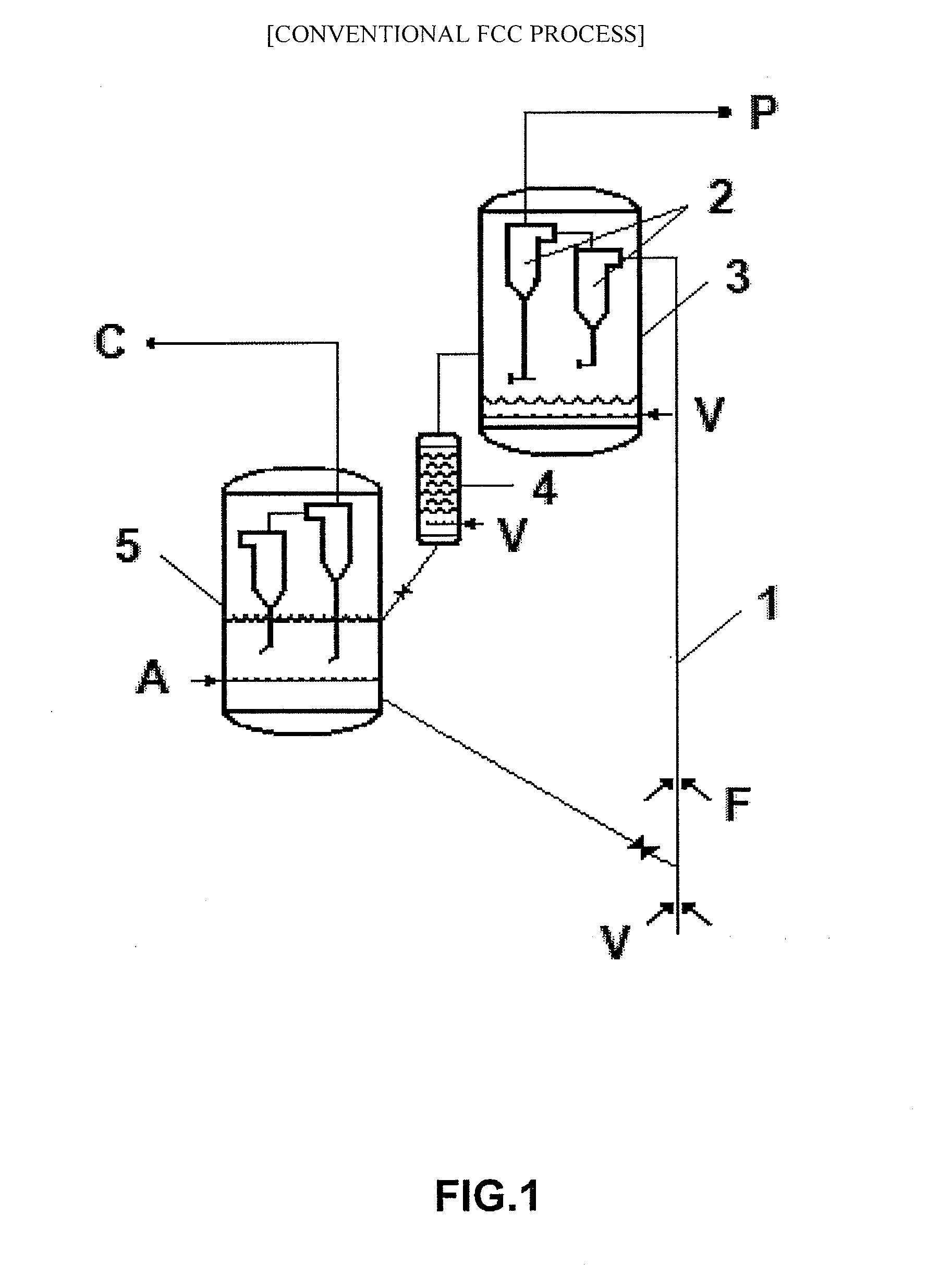
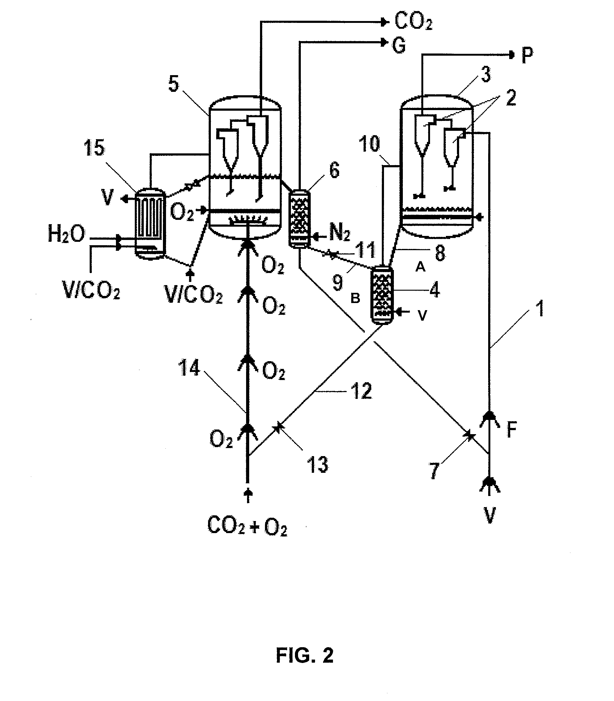
Fluid catalytic cracking process with reduced carbon dioxide emission
a fluid catalytic cracking and carbon dioxide technology, applied in catalytic cracking, hydrocarbon oil treatment, chemical/physical processes, etc., can solve the problems of large-scale equipment and considerable energy consumption, negative impact on operation, and large amount of energy, so as to achieve the effect of optimizing the overall process of fcc and practic avoiding the emission of co2
- Summary
- Abstract
- Description
- Claims
- Application Information
AI Technical Summary
Benefits of technology
Problems solved by technology
Method used
Image

Examples
example
[0065]Hereinafter, the present invention will be further specifically described with examples. However, the present invention is not limited to these examples.
[0066]The example below seeks merely to illustrate how effective the operation of the catalyst regeneration phase is, the major part of this invention, without however, being considered a limiting factor of its overall content. Regeneration of a catalyst, typical of the FCC process, containing a coke content situated in the range of between 0.7% and 2% in weight, was performed using an oxidant gas containing a mixture per volume of 21% O2 and 79% He, to simulate regeneration carried out with air and compared with another regeneration operated under identical conditions to the former but this time employing pure O2 as oxidant gas.
[0067]The temperature of the reaction was raised linearly at a rate of 10° C. per minute from room temperature up to 1000° C. The results obtained are shown in Table 1.
TABLE 1Maximum coke combustionCon...
PUM
 Abstract
Description
Claims
Application Information