
Magnetic random access memory, method of initializing magnetic random access memory and method of writing magnetic random access memory

a random access memory and magnetic random access technology, applied in the field of magnetic random access memory, can solve the problems that the method of generating the pin potential, jp-p 2005, does not become effective on the mram, and achieves the effect of easy initialization of the domain wall position, small number of processes, and large capacity

Active Publication Date: 2011-06-30
NEC CORP
View PDF7 Cites 6 Cited by
  • Summary
  • Abstract
  • Description
  • Claims
  • Application Information

AI Technical Summary

Benefits of technology

[0024]An object of the present invention is to provide a current drive domain wall motion MRAM that is adaptable for a miniaturization of an element and has a structure in which the number of processes is small, and a method of initializing a MRAM that introduces a domain wall into its structure and carries out an initialization.
[0031]According to the present invention, in a domain wall motion MRAM that uses a magnetic layer having a vertical magnetic anisotropy, it is possible to easily initialize a domain wall position. As a result, it is possible to provide the MRAM that has the large capacity and the small number of processes.

Problems solved by technology

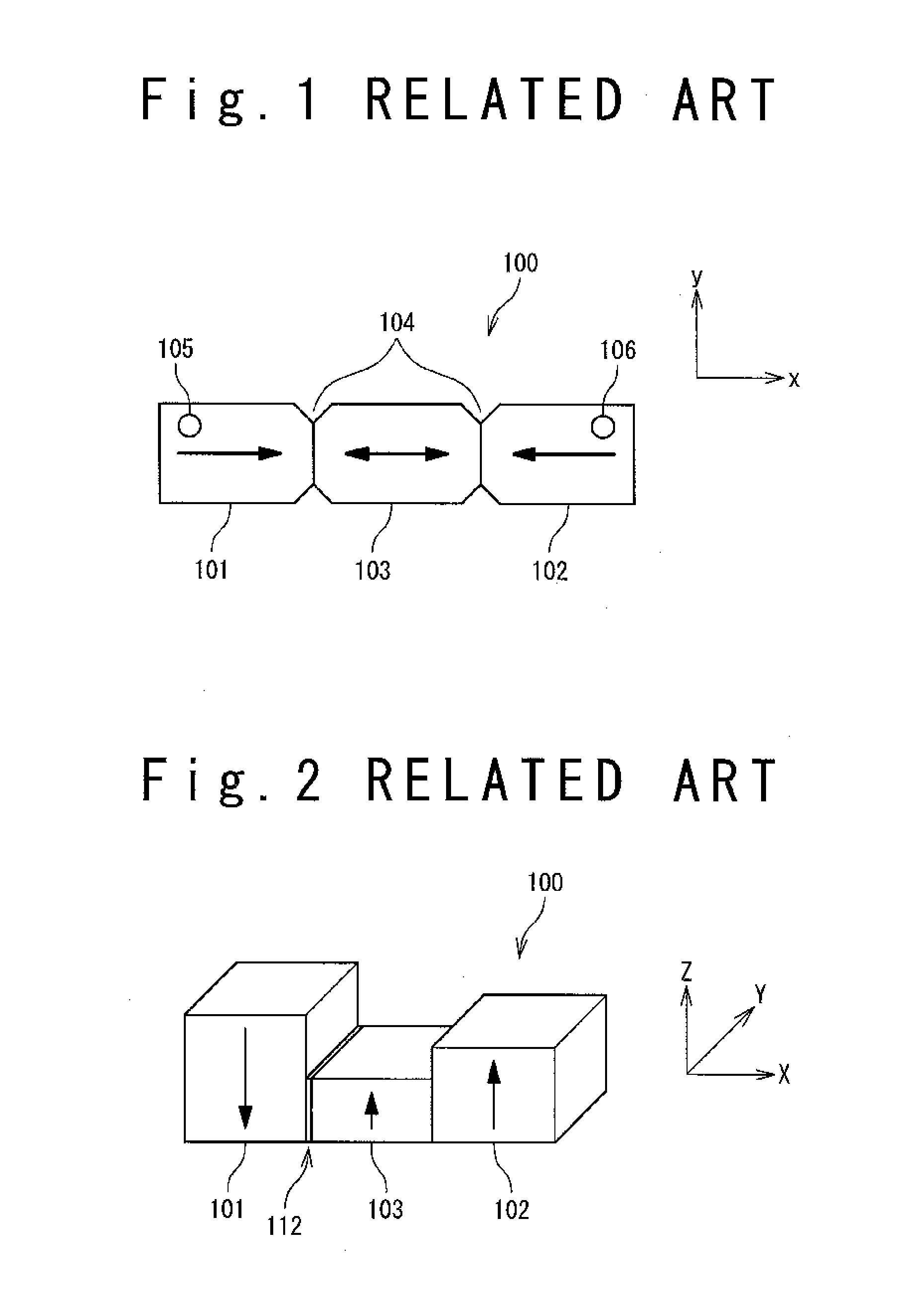
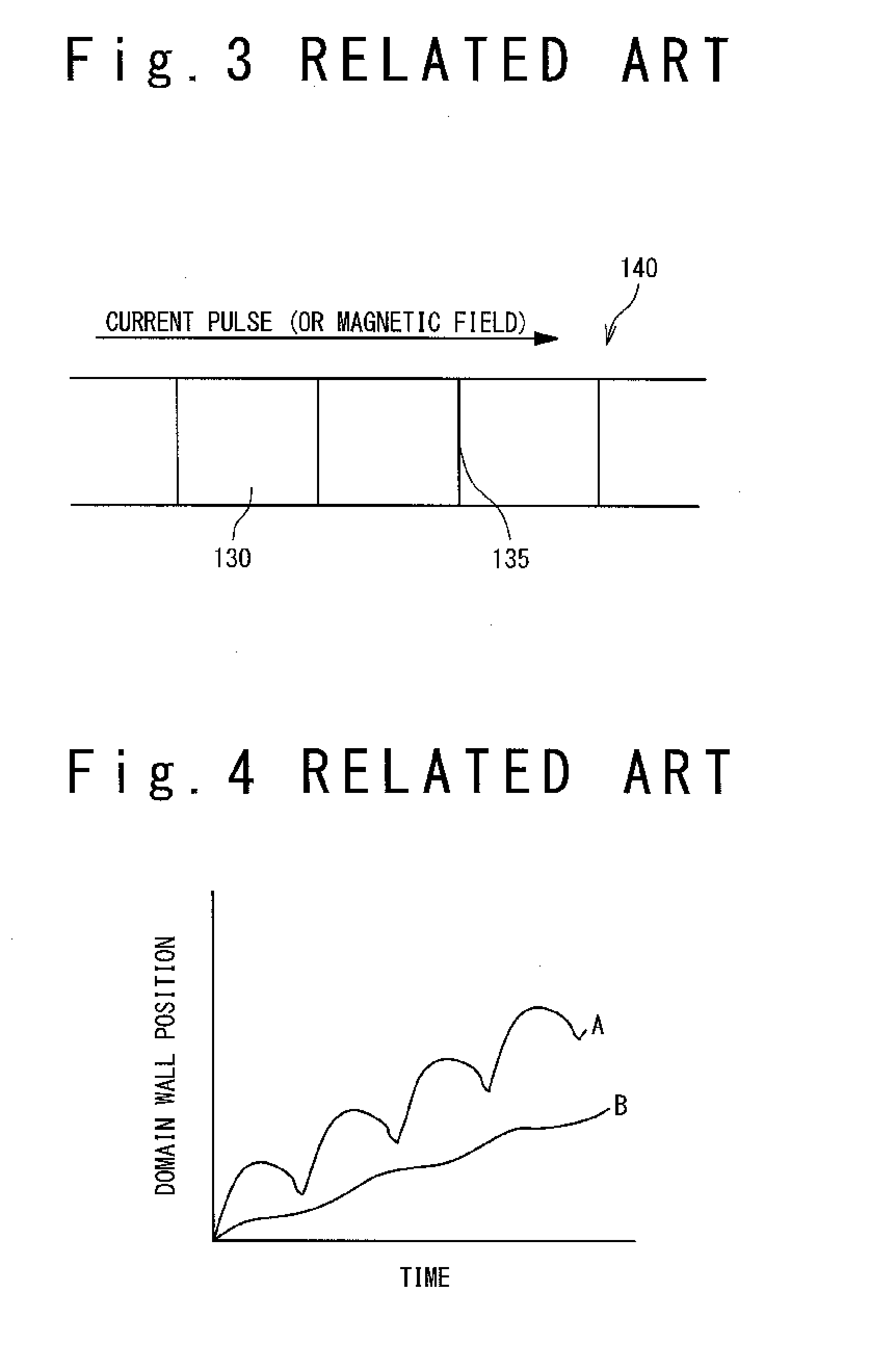
However, there is concern that the method of generating the pin potentials disclosed in the above JP-P 2005-191032A does not become effective on the MRAM, which uses the current drive domain wall motion.
That is, it is difficult to form the constrictions as described in JP-P 2005-191032A when the width of the magnetization recording layer is narrow, and there is a possibility that the process with the precision equal to or higher than a lithography limit of a semiconductor process is required.
This implies the increase in the number of processes, and there is concern that this leads to a factor of the cost increase.
Also, in the case of the method of JP-P 2008-34808A, there is an aspect that it is unsuitable for the MRAM to be applied, in which the miniaturization of a cell size is required, because the domain wall motion distance is uniquely determined.

Method used


Image

  • Magnetic random access memory, method of initializing magnetic random access memory and method of writing magnetic random access memory
  • Magnetic random access memory, method of initializing magnetic random access memory and method of writing magnetic random access memory
  • Magnetic random access memory, method of initializing magnetic random access memory and method of writing magnetic random access memory

Examples


Embodiment Construction

[0050]A MRAM according to an exemplary embodiment of the present invention and a method of initializing a MRAM will be described below with reference to attached drawings.

[0051]The MRAM according to the exemplary embodiment is a domain wall motion MRAM that uses a magnetic layer having a vertical magnetic anisotropy.

1. Configuration of Magnetic Memory Cell

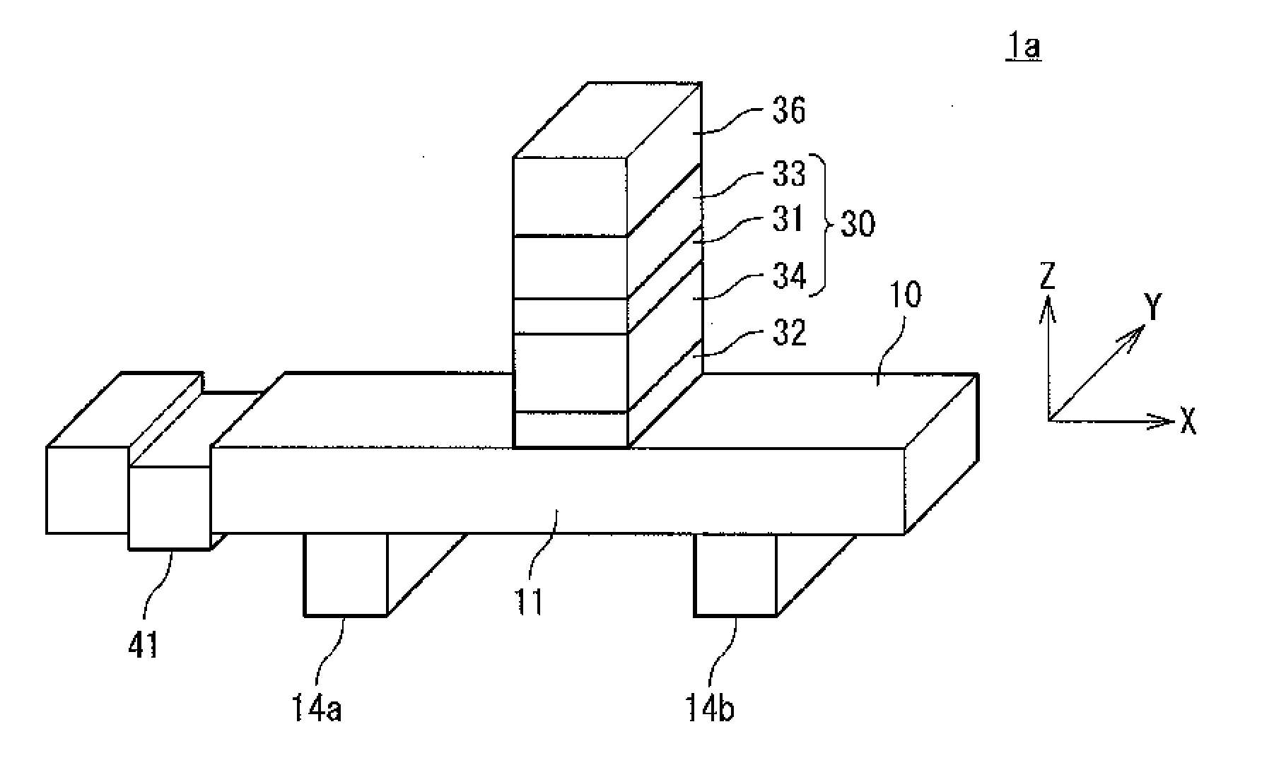
[0052]At first, a configuration of a magnetic memory cell used in the MRAM will be described. FIG. 5 is a perspective view showing one example of a magnetoresistive element in the magnetic memory cell according to the present exemplary embodiment. A magnetoresistive element 1 includes a magnetization recording layer 10, a tunnel barrier layer (non-magnetic layer) arranged on a first region 11 in the magnetization recording layer 10, and a pinned layer (magnetization pinned layer) arranged on the tunnel barrier layer 32. Here, the first region 11 is the region included in the magnetization recording layer 10 and located between a fi...


PUM


Abstract

A magnetic memory includes a magnetization recording layer, a first terminal, a second terminal, a magnetization pinned layer and a non-magnetic layer. The magnetization recording layer has a vertical magnetic anisotropy and includes a ferromagnetic layer. The first terminal is connected to one end of a first region in the magnetization recording layer. The second terminal is connected to the other end of the first region. The non-magnetic layer is arranged on the first region. The magnetization pinned layer is arranged on the non-magnetic layer and is located on the side opposite to the first region. The magnetization recording layer includes: a first extension portion located outside the first terminal in the magnetization recording layer; and a property changing structure that is arranged in the first extension portion and substantially changes a magnetization switching property of the magnetization recording layer.

Description

TECHNICAL FIELD[0001]The present invention relates to a magnetic random access memory (hereafter, referred to as MRAM), and more particularly relates to a domain wall motion MRAM.BACKGROUND ART[0002]MRAM is a nonvolatile memory that is promising from the viewpoint of a high integration and a high speed operation. In the MRAM, a magnetoresistive element indicating the magnetoresistive effect such as the TMR (Tunnel MagnetoResistance) effect is used. In the magnetoresistive element, for example, MTJ (Magnetic Tunnel Junction) in which a tunnel barrier layer is sandwiched between two ferromagnetic layers is formed. The two ferromagnetic layers are provided with: a magnetization pinned layer (pinned layer) in which a magnetization direction is pinned; and a magnetization free layer (free layer) in which a magnetization direction can be switched.[0003]A resistance value (R+ΔR) of the MTJ when the magnetization directions of the pinned layer and the free layer are anti-parallel becomes hi...

Claims


Application Information

Patent Timeline
IPC IPC(8): G11C11/14H01L29/82
CPCG11C11/15H01L43/08H01L27/228G11C11/1659G11C11/161G11C11/1675H10B61/22H10N50/10
Inventor SUZUKI, TETSUHIROFUKAMI, SHUNSUKENAGAHARA, KIYOKAZUOHSHIMA, NORIKAZUISHIWATA, NOBUYUKI
Owner NEC CORP
Learn More