Non-aqueous electrolyte secondary cell

a secondary cell, non-aqueous electrolyte technology, applied in the direction of cell components, final product manufacturing, sustainable manufacturing/processing, etc., can solve the problems of affecting cell characteristics, deteriorating storage characteristics of cells, and significant reduction of cell pack performan

Inactive Publication Date: 2011-06-30
SANYO ELECTRIC CO LTD
View PDF3 Cites 26 Cited by
  • Summary
  • Abstract
  • Description
  • Claims
  • Application Information

AI Technical Summary

Benefits of technology

[0027]As stated above, according to the configuration of the present invention, since elution of the transition metal from the positive electrode active material is prevented, when a compound

Problems solved by technology

In addition, when a cell pack was formed by connecting multiple of such cells in series, and when variations in capacity occurs in even one cell of the cell pack, an overdischarge cell or an overcharge cell was generated in the cell pack, and thus performance of the cell pack was significantly decreased.
There is a cause due to an insulation tape used in the non-aqueous electroly

Method used


Image

  • Non-aqueous electrolyte secondary cell
  • Non-aqueous electrolyte secondary cell
  • Non-aqueous electrolyte secondary cell

Examples


embodiment

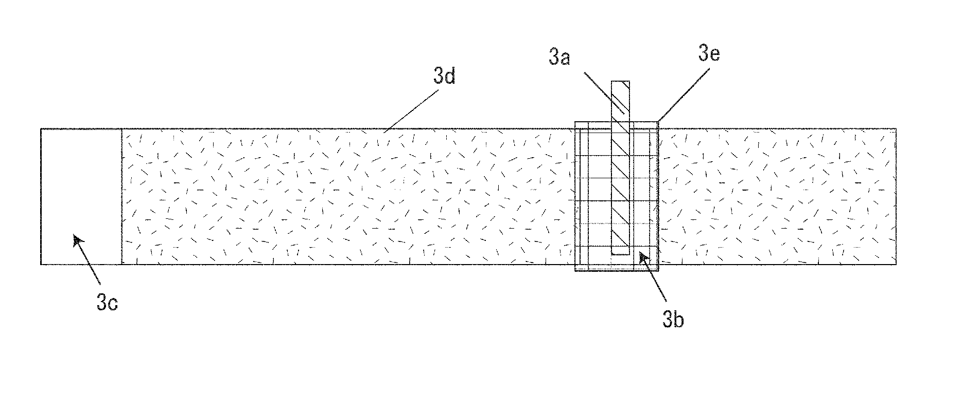
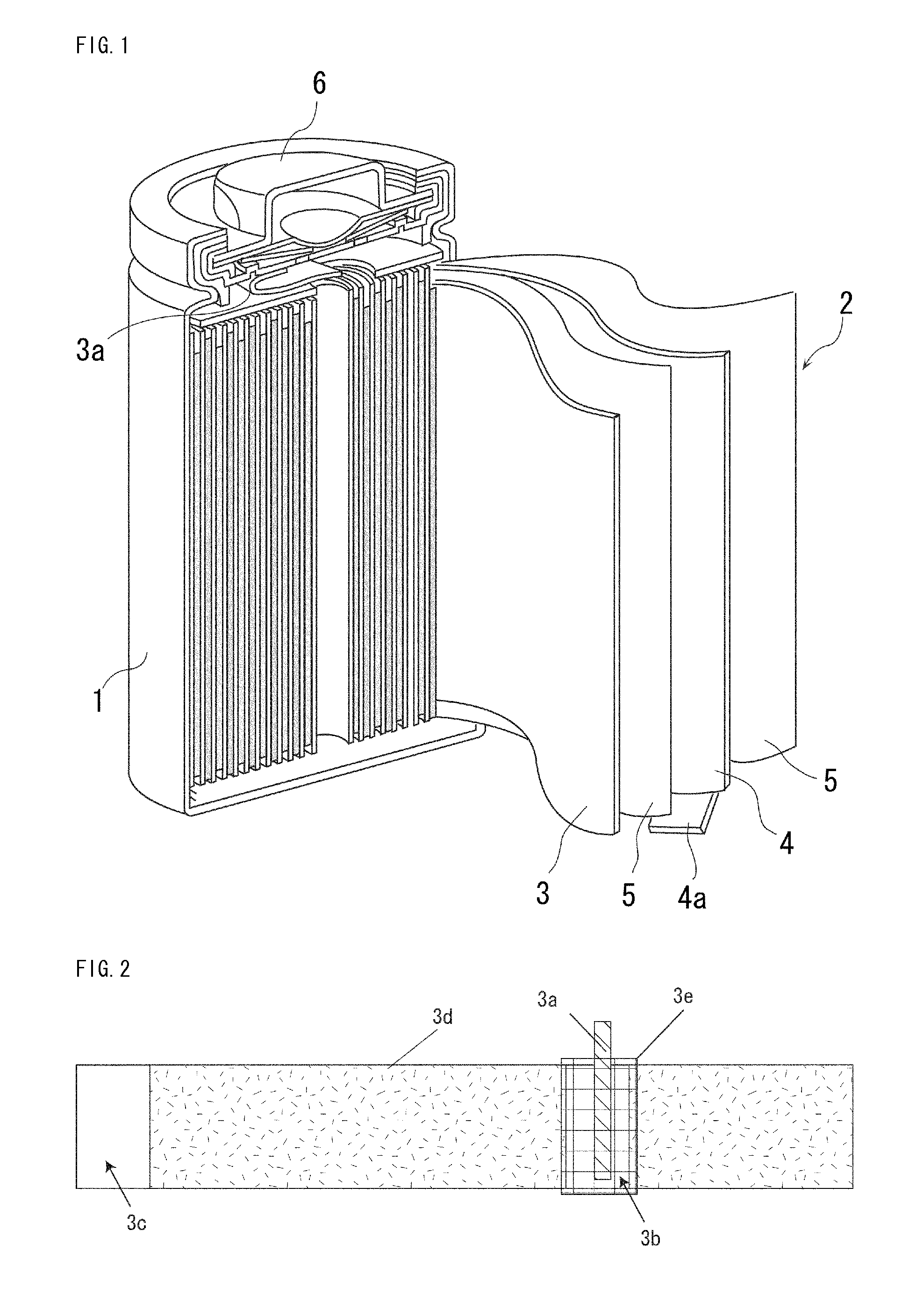
[0048]With reference to FIG. 1, the cell according to Embodiment is explained. FIG. 1 shows a perspective view of a dismantled cross-sectional area in the cell of the present invention, and FIG. 2 is a diagram showing the positive electrode where the positive electrode current collector tab is attached and the insulation adhesive tape is applied.

[0049]As shown in FIG. 1, in the cell according to the invention, an electrode assembly 2 comprising a separator 5, a positive electrode 3 and a negative electrode 4 is inserted into a cylindrical outer can 1. The opening of the outer can 1 is sealed by a sealing body 6. A negative electrode 4 is electrically connected to the outer can 1 via a negative electrode current collector tab 4a, while a positive electrode 3 is electrically connected to the sealing body 6 via a positive electrode current collector tab 3a. In a word, the outer can 1 also serves as a negative external terminal, and the sealing body 6 also serves as a positive external ...

example 1

Preparation of Positive Electrode

[0056]Lithium cobalt composite oxide as a positive electrode active material, acetylene black as a conductive agent and polyvinylidene fluoride as a binder were mixed in a mass ratio of 90:5:5. Then, the resulting mixture was dispersed in N-methylpyrrolidone as a solvent to form a positive electrode active material slurry. This slurry was applied on a positive electrode core made of aluminum foil with 15 μm thickness to prepare a positive electrode active material layer 3d including core exposed portions 3b and 3c. Thereafter, the resulting product was dried, rolled and cut to a desired size. Then, a positive electrode collector tab 3a was attached to the core exposed portion 3b of the middle portion, and further the above Tape 1 as an insulation adhesive tape 3e was applied on the positive electrode collector tab as shown in FIG. 2, thus preparing a positive electrode 3. This insulating tape was 2.7 mm higher and 2.5 mm wider than the core exposed p...

reference example 1

[0063]A non-aqueous electrolyte secondary cell according to Reference Example 1 was fabricated in a similar way to Example 1 except that the insulating adhesive tape was not applied.

(Storage Test in Charged State)

[0064]For each of Example 1, Comparative Examples 1 and 2, and Reference Example 1, two hundred non-aqueous electrolyte secondary cells were fabricated. Next, these cells were charged at a constant current of 0.7 It (1750 mA) to a voltage of 4.2V, and then charged at a constant voltage to a current of 0.02 It (50 mA). Then, the voltages of these cells were measured at 25° C. Thereafter, these cells were discharged at a constant current of 1.0 It (2500 mA) to a voltage to 3.0V, and the discharge capacity in this point (initial capacity) was measured.

[0065]Thereafter, these cells were charged at a constant current of 0.7 It (1750 mA) to a voltage of 4.2V, and then charged at a constant voltage to a current of 0.02 It (50 mA). After this, half of the cells (100 each) were stor...


PUM

PropertyMeasurementUnit
Fractionaaaaaaaaaa
Fractionaaaaaaaaaa
Fractionaaaaaaaaaa

Abstract

According to the invention, there can be provided a non-aqueous electrolyte secondary cell whose capacity is hardly decreased even stored at high temperatures in a charged state.
The non-aqueous electrolyte secondary cell uses an insulation adhesive tape composed of a base material and a glue material. And in an absorbance spectra of the glue material measured using an infrared spectrophotometer so that the maximum peak intensity is 5 to 20% in transmittance, when peak intensities for C—H stretching vibration of 3040 to 2835 cm−1 and C═O stretching vibration of 1870 to 1560 cm−1 are respectively defined as I(C—H) and I(C═O), a peak intensity ratio represented by I(C═O)/I(C—H) is 0.01 or less.

Description

BACKGROUND OF THE INVENTION[0001]1. Field of the Invention[0002]The present invention relates to an improvement of a non-aqueous electrolyte secondary cell.[0003]2. Background Art[0004]Today, mobile information terminals such as mobile phones and laptop computers have been rapidly enhanced in functionality and compactness and reduction in weight. As the driving power sources for these terminals, nonaqueous electrolyte secondary cells represented by lithium ion secondary cells, which have high energy density and high capacity, are widely used.[0005]In particular, in the case of a nonaqueous electrolyte secondary cell using a spiral electrode assembly in which the strip-form positive and negative electrodes are wound spirally via a separator, since the area where the positive and negative electrodes face each other is large, high electric current can be easily taken out. For this reason, a non-aqueous electrolyte secondary cell using a spiral electrode assembly is widely used as a dri...

Claims


Application Information

Patent Timeline
IPC IPC(8): H01M2/16H01M2/18C09J7/38C09J7/22
CPCY02E60/122H01M4/13H01M4/366H01M4/505H01M4/525C09J2479/086H01M10/052C09J7/0246C09J2201/622C09J2409/00H01M4/62C09J7/38C09J7/22C09J2301/312Y02E60/10Y02P70/50H01M50/595H01M50/531H01M2004/021
Inventor KOBAYASHI, KAZUMAHIROTA, YOHEIMORIKAWA, YUKIKATO, YOSHIOKUSUMOTO, YASUYUKIMATSUTA, SHIGEKI
Owner SANYO ELECTRIC CO LTD
Why Eureka
Try Eureka