
Low compressive load seal design for solid polymer electrolyte fuel cell

Inactive Publication Date: 2011-06-30
DAIMLER AG
View PDF6 Cites 12 Cited by
  • Summary
  • Abstract
  • Description
  • Claims
  • Application Information

AI Technical Summary

Benefits of technology

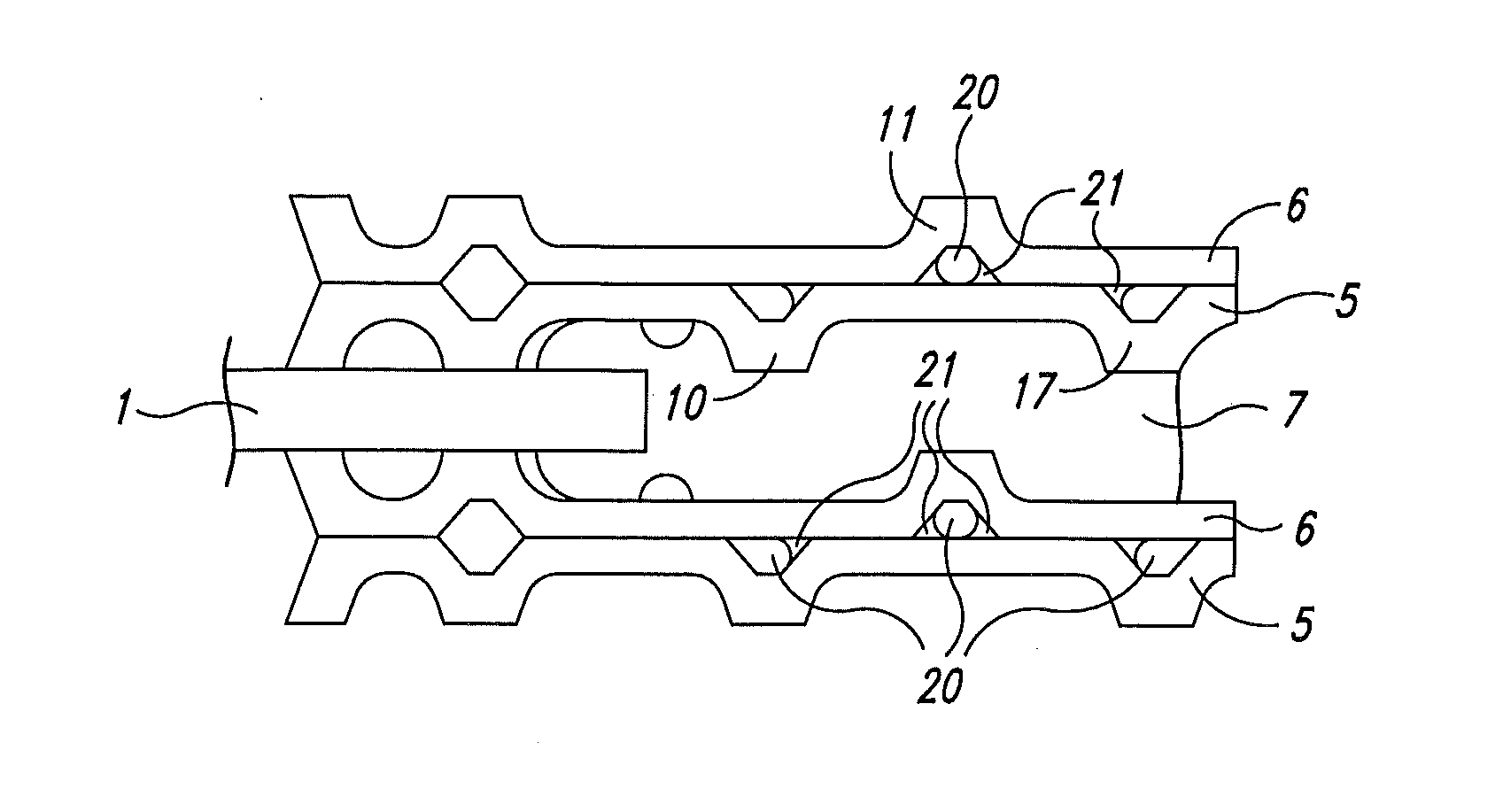
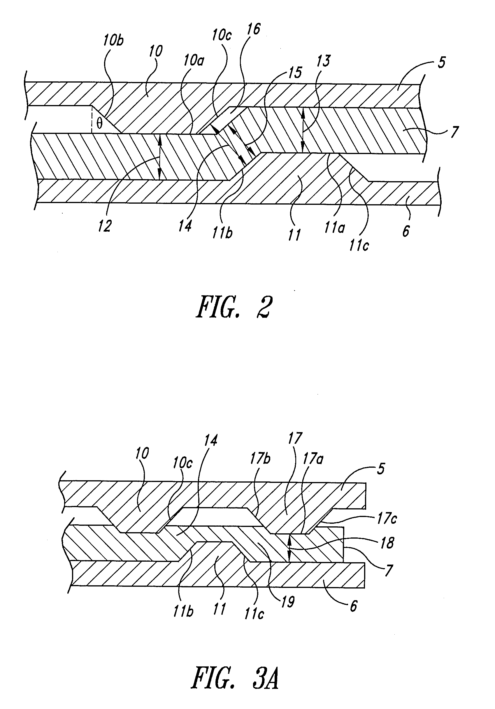
[0009]A low compressive load seal for a solid polymer fuel cell can be achieved using a seal design that employs two offset peripheral projections, one on each of the anode and cathode separator plates, to compress a gasket. The design can achieve a seal against a given burst pressure with a lower load normal to the separator plates. This is done by creating significant compression of the gasket parallel to the separator plates (as opposed to be perpendicular to them) in the gap between the projections. This allows for a thinner fuel cell design without requiring impractical tolerances on the thicknesses of the cell components.

Problems solved by technology

This can be challenging because the MEA is typically a relatively large, thin sheet, and thus a seal may be needed over a significant perimeter, and a fuel cell stack typically involves sealing numerous MEAs.
As fuel cell thickness decreases, fuel cell makers face a challenge in accommodating the possible variations allowed within the component thickness tolerances.
For instance, with so many thinner cells involved, the tolerance stackup may result in insufficient compression of certain seals and / or gaskets if certain components are at the thin end of a tolerance range.
Conversely however, the tolerance stackup may result in excessive stress on the seal material and overcompression and damage to certain cell components (e.g., flow field distribution channels) if certain components are at the thick end of a tolerance range.

Method used


Image

  • Low compressive load seal design for solid polymer electrolyte fuel cell
  • Low compressive load seal design for solid polymer electrolyte fuel cell
  • Low compressive load seal design for solid polymer electrolyte fuel cell

Examples


examples

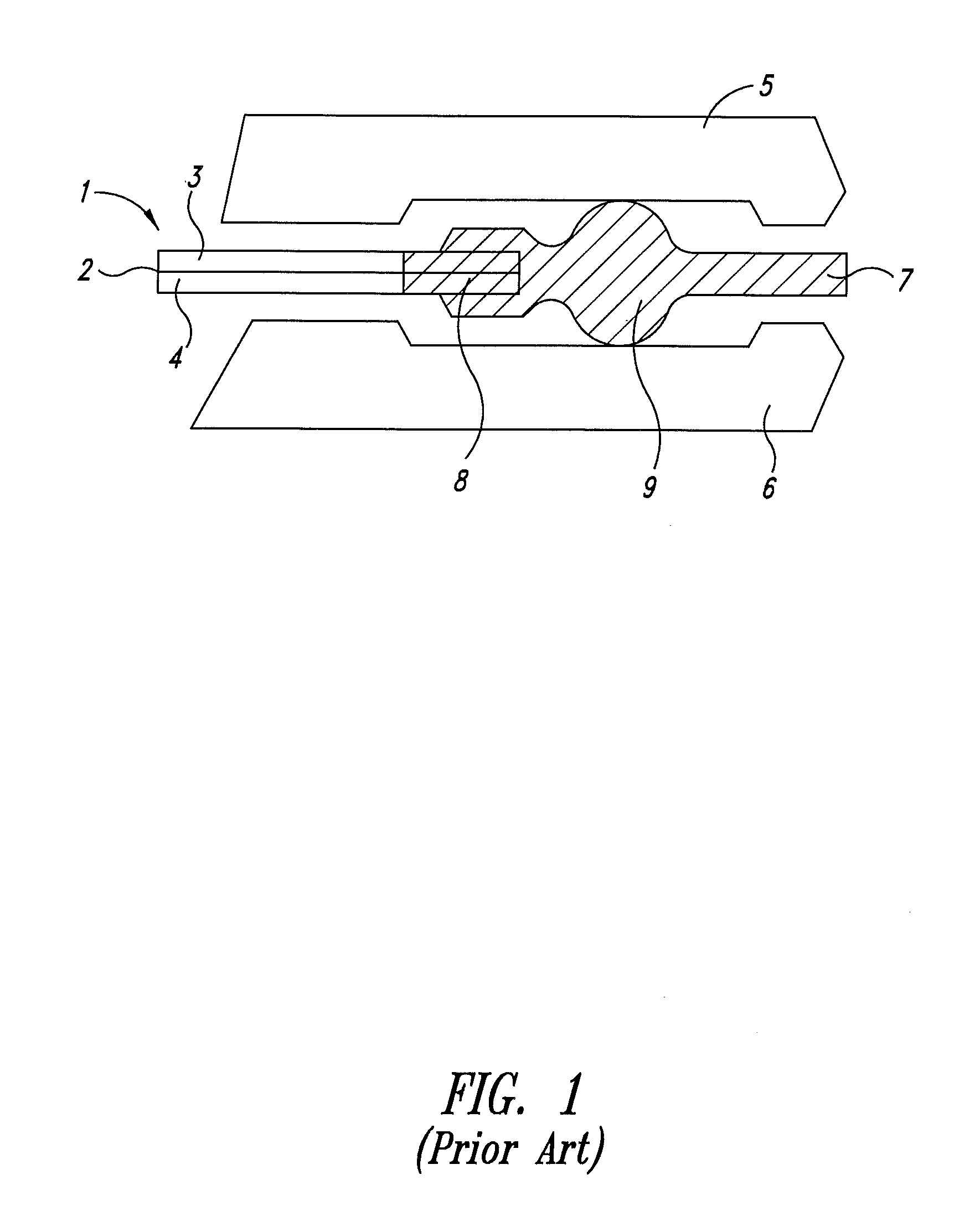
[0042]A calculated comparison was made between a Comparative prior art O-ring type gasket / seal design for a fuel cell and that of an Inventive gasket / seal design. Qualitatively, the Comparative design was like that depicted in FIG. 1 while the Inventive design was like depicted in FIG. 3A. In the Comparative example, the O-ring was a silicon based elastomer that was 1.85 mm in diameter. For purposes of calculation, the O-ring was assumed to be compressed between flat separate plate surfaces. In the Inventive Example, the gasket was made of the same material and was flat with a thickness of 0.5 mm. Further, the separator plate projections were all 0.25 mm in height, 0.23 mm in width, and had sidewall angles that were 45 degrees from a normal direction to the separator plates. (Only a two projection design was actually considered in these calculations, as it was assumed that the results would be symmetrical about the cathode projection 11.)

[0043]FIG. 4A shows the predicted burst press...


PUM


Abstract

A low compressive load seal for a solid polymer fuel cell employs two offset peripheral projections, one on each of the anode and cathode separator plates, for compressing a gasket. The design can achieve a seal against a given burst pressure with a lower load normal to the separator plates by creating significant compression parallel to the separator plates in the gap between the offset projections. The design allows for thinner fuel cell constructions while avoiding the issues that arise in prior art designs (e.g., stress on seal material and component crushing) if reasonable tolerances were allowed for variations in component thickness.

Description

BACKGROUND[0001]1. Technical Field[0002]The present invention relates to gasket seal designs for solid polymer electrolyte fuel cells.[0003]2. Description of the Related Art[0004]Fuel cells are devices in which fuel and oxidant fluids electrochemically react to generate electricity. A type of fuel cell being developed for various commercial applications is the solid polymer electrolyte fuel cell, which employs a membrane electrode assembly (MEA) comprising a solid polymer electrolyte made of a suitable ionomer material (e.g., Nafion®) disposed between two electrodes. Each electrode comprises an appropriate catalyst located next to the solid polymer electrolyte. The catalyst may be, for example, a metal black, an alloy, or a supported metal catalyst such as platinum on carbon. The catalyst may be disposed in a catalyst layer, and the catalyst layer typically contains ionomer, which may be similar to that used for the solid polymer electrolyte. A fluid diffusion layer (a porous, elect...

Claims


Application Information

Patent Timeline
IPC IPC(8): H01M2/08H01M8/24H01M8/00
CPCH01M8/0247H01M8/0267H01M8/0273Y02E60/50H01M8/242H01M2008/1095H01M8/0297H01M8/0258
Inventor FARRINGTON, SIMONARTIBISE, ROBERT H.
Owner DAIMLER AG
Learn More