

Implantable graft assembly
a graft and assembly technology, applied in the field of intracorporeal implantable medical devices, can solve the problems of cerebral aneurysms that are exceptionally difficult to treat, stenosis of the trunk vessel or of the branch vessel, and turbulence flow, and achieves small surface area, low cost, and no blockage of the branch vessel
- Summary
- Abstract
- Description
- Claims
- Application Information
AI Technical Summary
Benefits of technology
Problems solved by technology
Method used
Image

Examples
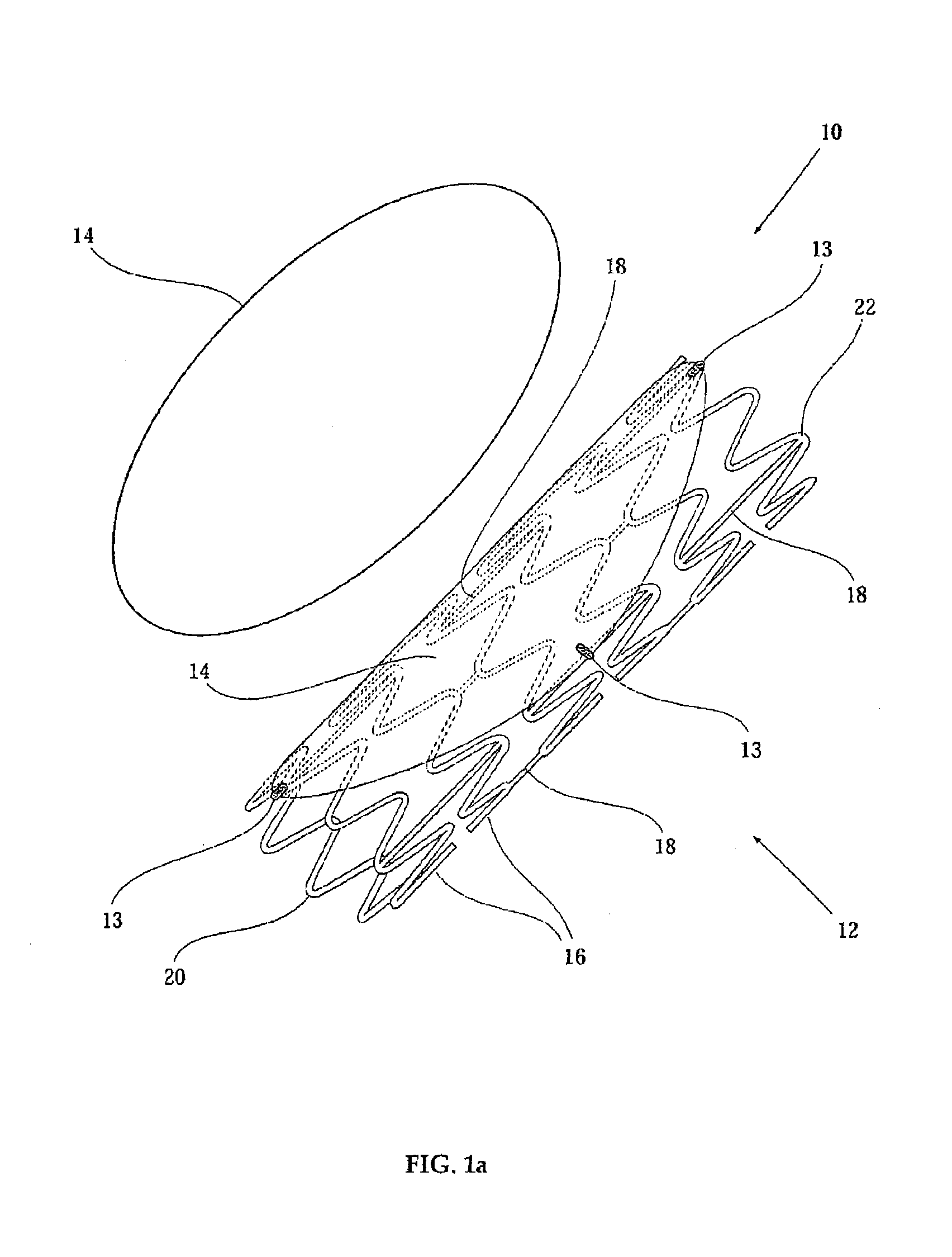
first embodiment
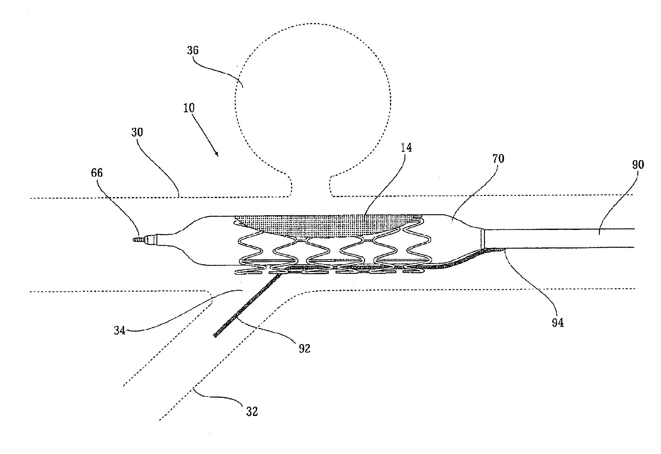
[0151]a delivery system including two guide wires where the orientation guide wire passes over the outside of a graft of a graft-assembly is depicted in FIG. 5. In FIG. 5 is depicted the distal end of delivery catheter 90. Delivery catheter 90 is similar to that of prior art balloon catheters known in the art of stent delivery, and includes the distal end of a catheter guiding guide wire 66 running through a guide wire lumen 68 from the proximal end (not depicted) of guide wire lumen 68 out through the distal end of guide wire lumen 68 at the distal end of catheter 90. Graft-assembly 76 including a substantially circular graft 14 is crimped over a balloon 70, balloon 70 configured to function in the usual way. Unlike prior art stent-delivery catheters, delivery catheter 90 includes an additional distal orientation guide wire lumen that runs from the proximal end of delivery catheter 90 (not depicted) to an orientation guide wire port 94 that is positioned proximally to balloon 70.
[0...
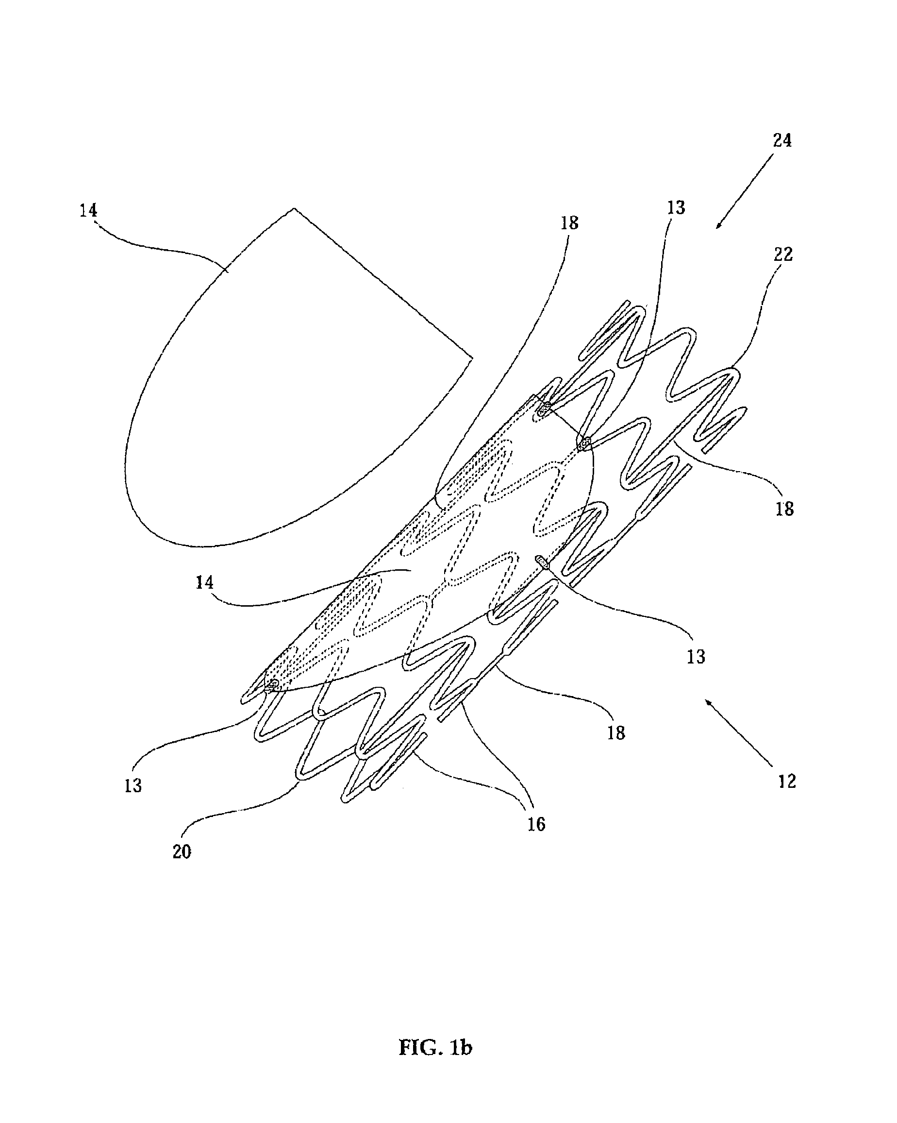
second embodiment
[0154]a delivery system including two guide wires where an orientation guide wire 92 passes between a delivery catheter 96 and a graft-assembly 106 to emerge through an alignment hole 102 reinforced with radio opaque grommet 104 penetrating through a graft 14 having a curved periphery with an elliptical shape is depicted in FIGS. 6A and 6B. FIGS. 6A and 6B depict the distal end of delivery catheter 96. Delivery catheter 96 is similar to that of prior art balloon catheters known in the art of stent delivery, and includes the distal end of a catheter guiding guide wire 66 running through a guide wire lumen 68 inside a main catheter shaft 98 from the proximal end (not depicted) of guide wire lumen 68 out through the distal end of guide wire lumen 68 at the distal end of delivery catheter 96. Graft-assembly 106 including graft 14 is crimped over a balloon 70, balloon 70 configured to function in the usual way.
[0155]Unlike prior art stent-delivery catheters, delivery catheter 96 includes...
PUM
| Property | Measurement | Unit |
|---|---|---|
| Angle | aaaaa | aaaaa |
| Angle | aaaaa | aaaaa |
| Angle | aaaaa | aaaaa |
Abstract
Description
Claims
Application Information