Image pickup device and solid-state image pickup element

a pickup device and image technology, applied in the direction of television system scanning details, radio control devices, television systems, etc., can solve the problems of low optical efficiency achieved, low optical efficiency of cameras, and low intensity of light falling on a single pixel, so as to improve optical efficiency and reduce the density of dispersive elements to be arranged per side , the effect of easy manufacturing

Inactive Publication Date: 2011-07-07
PANASONIC CORP
View PDF10 Cites 54 Cited by
  • Summary
  • Abstract
  • Description
  • Claims
  • Application Information

AI Technical Summary

Benefits of technology

[0031]The solid-state image sensor and image capture device of the present invention have a photosensitive cell array that receives light on both of their front and back surface sides, and also uses a dispersive element array that does not absorb the light, thus achieving higher optical efficiency. Optionally, the dispersive el

Problems solved by technology

Nevertheless, the greater the number of pixels in an image sensor, the lower the intensity of the light falling on a single pixel and the lower the sensitivity of camera tends to be.
That is why with such a color filter, the optical efficiency of a camera would decrease.
Specifically, in a color camera that uses a Bayer color filter, for example, a subtractive color filter that uses an organic pigment as a dye i

Method used


Image

  • Image pickup device and solid-state image pickup element
  • Image pickup device and solid-state image pickup element
  • Image pickup device and solid-state image pickup element

Examples


embodiment 1

[0069]First, a First Specific Preferred Embodiment of the present invention will be described. FIG. 3 is a block diagram illustrating an overall configuration for an image capture device as a first preferred embodiment of the present invention. The image capture device of this preferred embodiment is a digital electronic camera and includes an image capturing section 300 and a signal processing section 400 that receives a signal from the image capturing section 300 and outputs a signal representing an image (i.e., an image signal). The image capture device may either generate only a still picture or have the function of generating a moving picture.

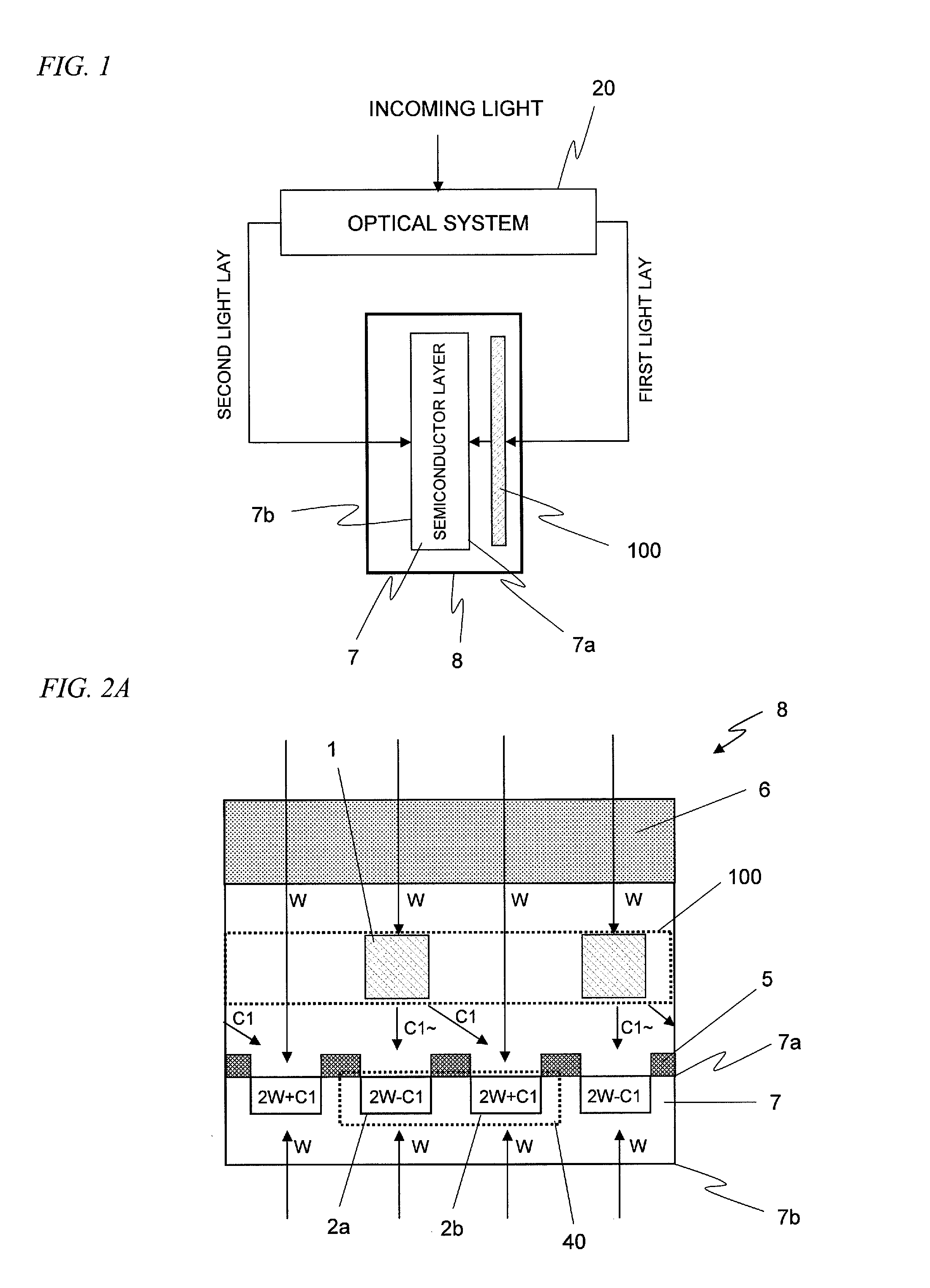
[0070]The image capturing section 300 includes an optical system 20 for imaging a given subject, a solid-state image sensor 8 (which will be simply referred to herein as an “image sensor”) for converting optical information into an electrical signal by photoelectric conversion, and a signal generating and receiving section 21, which not on...

embodiment 2

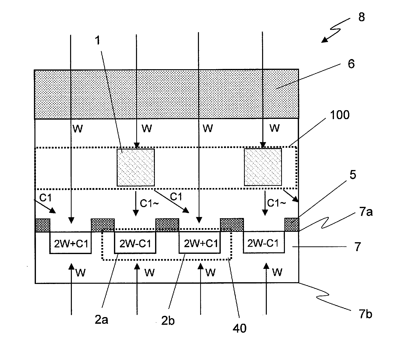
[0108]Hereinafter, a second preferred embodiment of the present invention will be described with reference to FIGS. 7A through 7C. The image capture device of this second preferred embodiment has dispersive elements with a different property from the counterparts of the image capture device of the first preferred embodiment described above but the other components of the second preferred embodiment are no different from those of the first preferred embodiment. Thus, the following description of the second preferred embodiment will be focused on only the difference from the image capture device of the first preferred embodiment and the description of their common features will be omitted herein.

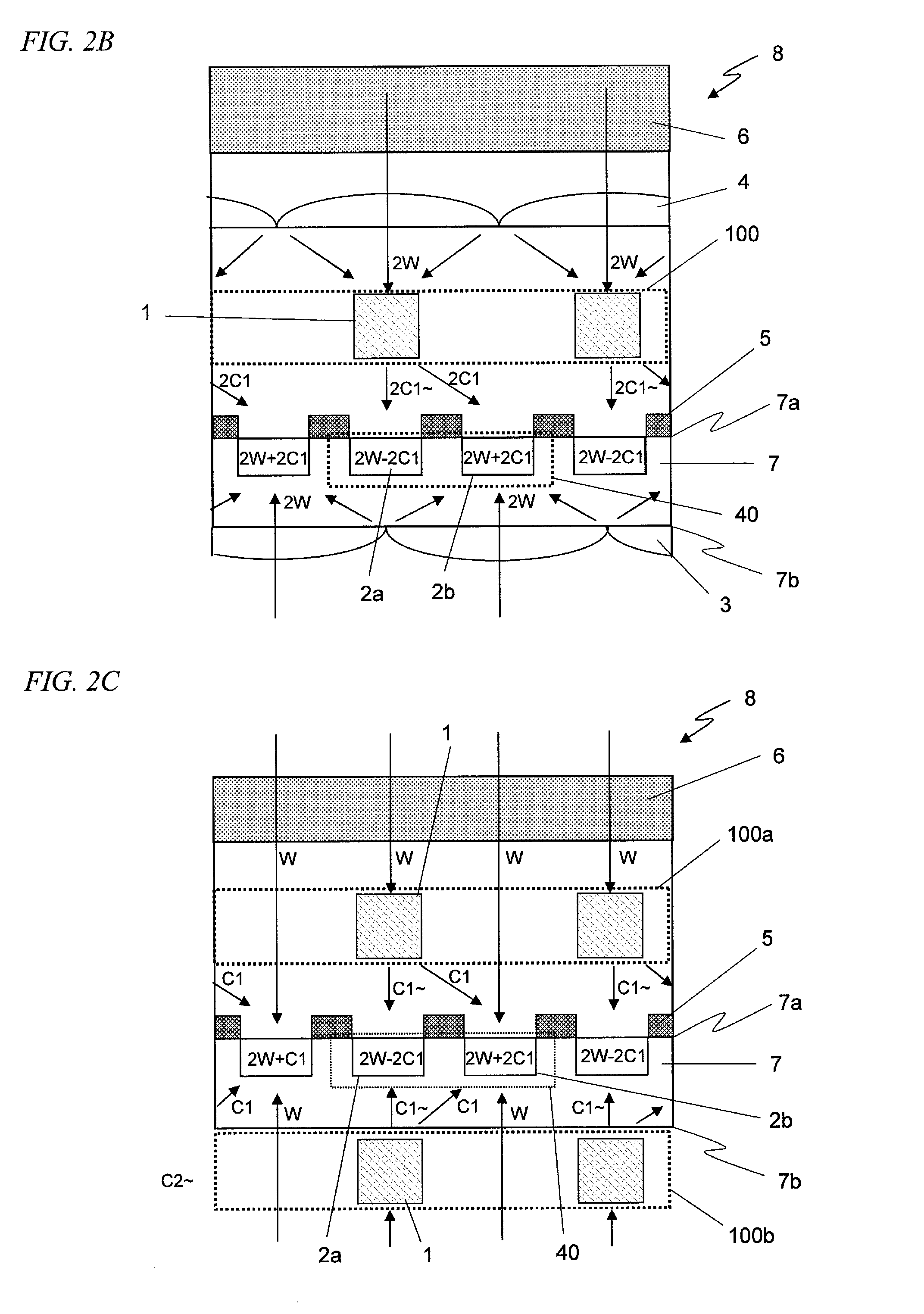
[0109]FIG. 7A is a plan view illustrating the pixel arrangement of the image sensor 8 of this preferred embodiment as viewed from over the front surface thereof. In this preferred embodiment, a matrix of pixels that are arranged in two columns and two rows is also used as a fundamental unit of...


PUM


Abstract

A solid-state image sensor according to the present invention includes: a semiconductor layer 7, which has a first surface and a second surface that is opposite to the first surface; a photosensitive cell array, which has been formed in the semiconductor layer 7 to receive light through both of the first and second surfaces; and at least one dispersive element array, which is arranged on the same side as at least one of the first and second surfaces so as to face the photosensitive cell array. The photosensitive cell array includes first and second photosensitive cells 2a and 2b. And the dispersive element array makes light rays falling within mutually different wavelength ranges incident on the first and second photosensitive cells 2a and 2b, respectively.

Description

TECHNICAL FIELD[0001]The present invention relates to a technique for increasing the sensitivity of a solid-state image sensor and capturing color information using such a solid-state image sensor.BACKGROUND ART[0002]Recently, the performance and functionality of digital cameras and digital movie cameras that use some solid-state image sensor such as a CCD and a CMOS (which will be simply referred to herein as an “image sensor”) have been enhanced to an astonishing degree. In particular, the size of a pixel structure for use in an image sensor has been further reduced these days thanks to rapid development of image capture device processing technologies, thus getting an even greater number of pixels and drivers integrated together in an image sensor. And the performance of image sensors has been further enhanced as well. Meanwhile, cameras that use a backside illumination type image sensor, which receives incoming light on its back surface side, not on its front surface side with a ...

Claims


Application Information

Patent Timeline
IPC IPC(8): H04N5/335
CPCH01L27/14625H01L27/1464H04N2209/047H04N9/045H01L27/14621H01L27/14627H01L27/146
Inventor HIRAMOTO, MASAONGUYEN, KHANGMONOBE, YUSUKENISHIWAKI, SEIJISUZUKI, MASAAKI
Owner PANASONIC CORP
Why Eureka
Try Eureka