Vacuum heat insulation material and manufacturing method therefor

a technology of heat insulation material and vacuum, applied in the field of vacuum insulation material, to achieve the effect of suppressing reducing the thickness of the thinnest part, and preventing the occurrence of pinholes

Active Publication Date: 2011-07-07
PANASONIC CORP
View PDF7 Cites 70 Cited by
  • Summary
  • Abstract
  • Description
  • Claims
  • Application Information

AI Technical Summary

Benefits of technology

[0031]Usually, as a measure for preventing occurrence of pinholes, it is believed effective to increase the thickness of the sealant layer at the innermost layer of the laminate film facing the inside of the vacuum insulation material, but by increasing the thickness of the sealant layer, it may be feared that the area of the gas invasion path at the section of the sealing part may be widened.
[0032]In the vacuum insulation material of the present invention, since the gas invasion amount can be controlled in the thin-wall parts, if the thickness of the sealant layer is increased, it is possible to suppress the increase of gas and moisture invading into the inside of the vacuum insulation material through the sealing part from the end surface of the laminate film peripheral edge.
[0033]According to the configuration of the present invention, if a thin-wall part reduced in thickness in a part of the sealant layer is formed in the sealing part, in the thin-wall part of the sealant layer provided in the sealing part and in its vicinity, cracks and breakages of the sealing part can very hardly occur. Further, it is easy to reduce the thickness of the thinnest part of the thin-wall part, and the sealing part having the thin-wall part is hardly peeled by an external force, and there is a very slight effect of heat bridge, so that a vacuum insulation material maintaining an excellent adiabatic performance for a long period can be presented.

Problems solved by technology

However, considering the adsorbing capacity of the existing adsorbents, it seems insufficient by the use of adsorbents alone in order to present a vacuum insulation material capable of maintaining a high adiabatic effect for a long period, and it is necessary to add any means for suppressing the amount of atmospheric gas infiltrating into the vacuum insulation material.

Method used


Image

  • Vacuum heat insulation material and manufacturing method therefor
  • Vacuum heat insulation material and manufacturing method therefor
  • Vacuum heat insulation material and manufacturing method therefor

Examples


embodiment 1

Preferred Embodiment 1

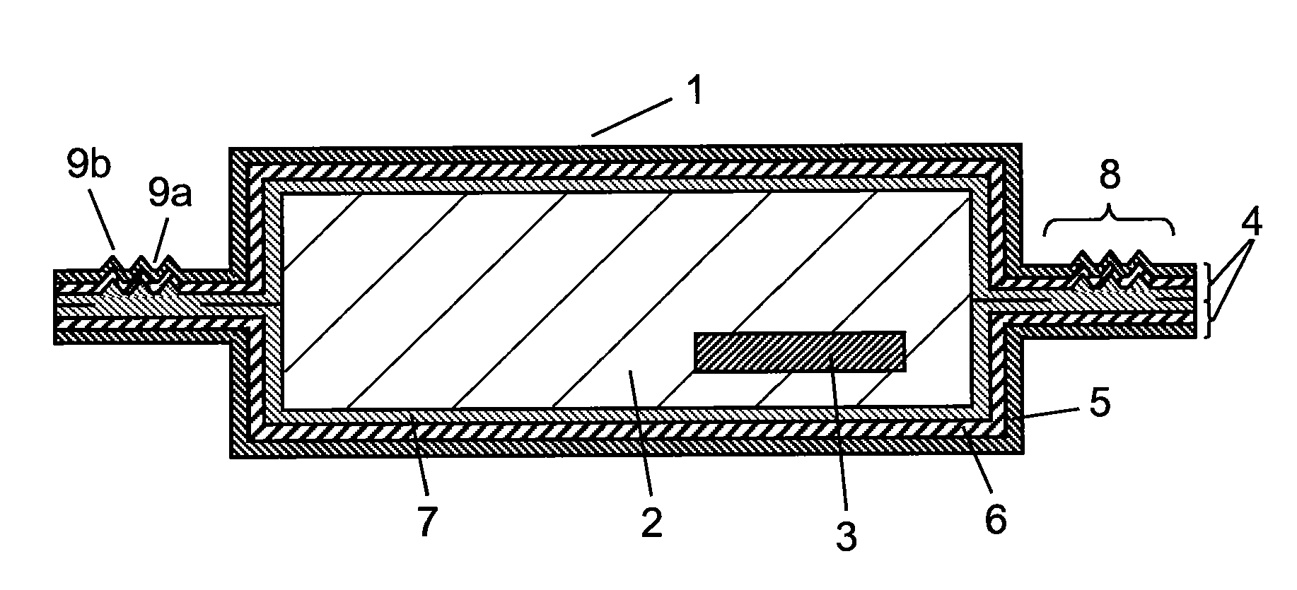
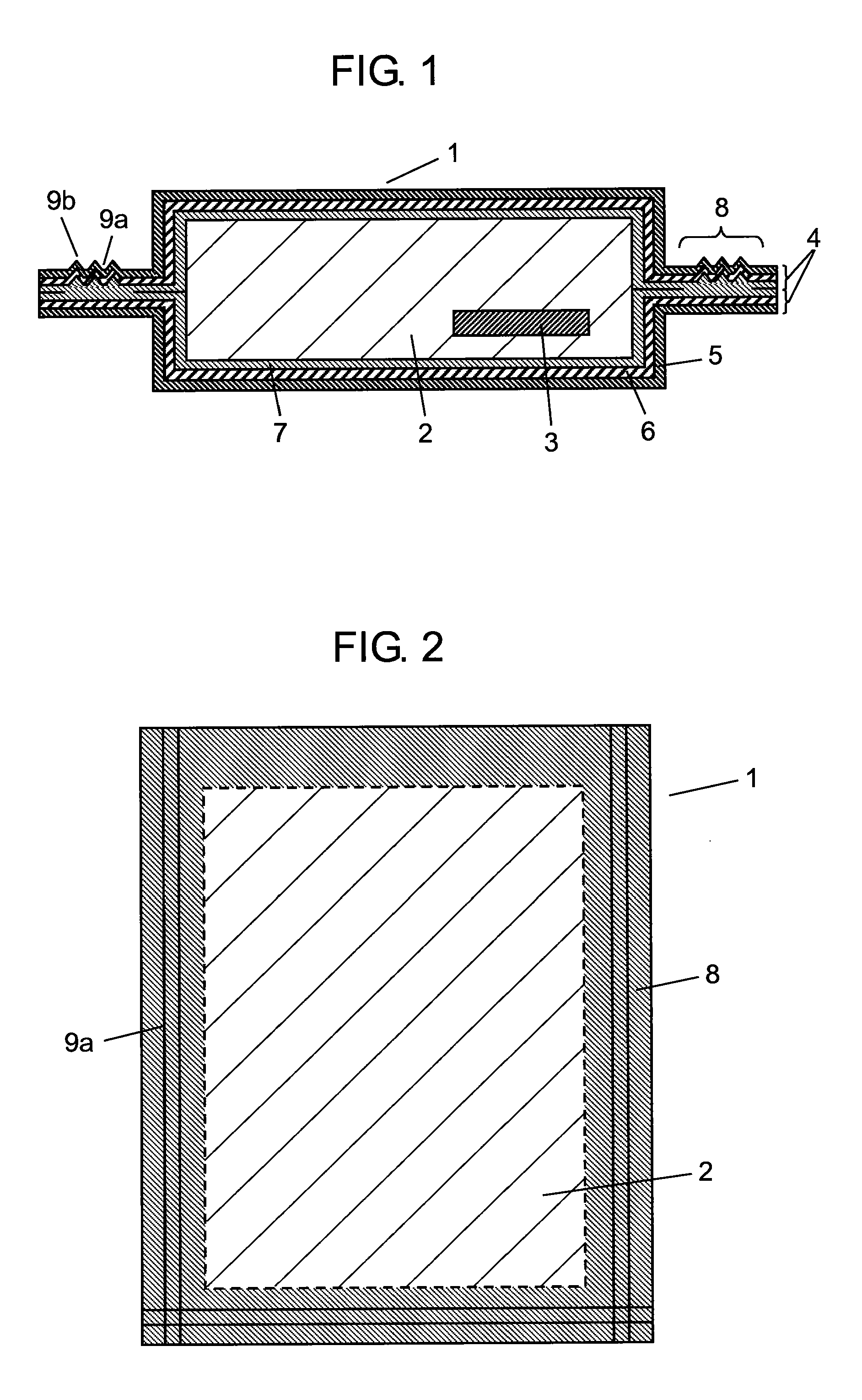
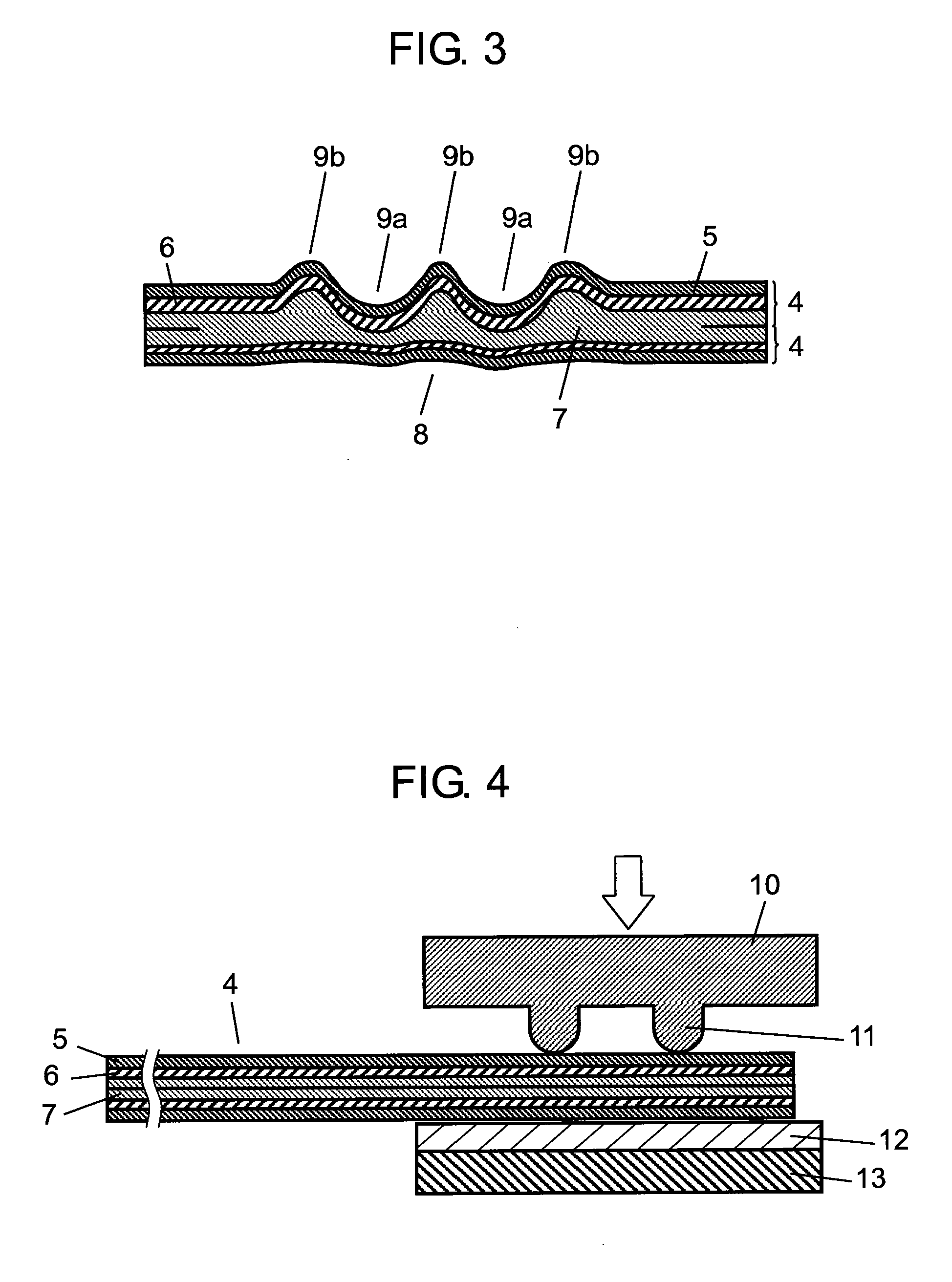
[0061]FIG. 1 is a sectional view of a vacuum insulation material in preferred embodiment 1 of the present invention. FIG. 2 is a plan view of the vacuum insulation material of the preferred embodiment. FIG. 3 is a sectional view showing a sealing part having a thin-wall part and a thick-wall part of the vacuum insulation material of the preferred embodiment. FIG. 4 is a sectional view showing an example of a heating and pressing operation of an laminate film by a pressing and compressing jig of the vacuum insulation material of the preferred embodiment. FIG. 5 is a plan view of other example of the vacuum insulation material in preferred embodiment 1 of the present invention. FIG. 6 is a sectional view of a modified example of the sealing part having the thin-wall part and the thick-wall part of the vacuum insulation material in preferred embodiment 1 of the present invention.

[0062]As shown in FIG. 1, vacuum insulation material 1 of the preferred embodiment inc...

first exemplary embodiment

[0112]In preferred embodiment 1, sealant layer 7 is a straight-chain low-density polyethylene film of thickness of 50 μm, gas barrier layer 6 is an aluminum foil of thickness of 6 μm and protective layer 5 is a nylon film of two layers of thickness of 15 μm and 25 μm, which were laminated to form laminate film 4. This laminate film 4, core material 2 composed of glass fiber, and adsorbent 3 composed of calcium oxide were combined to compose vacuum insulation material 1.

[0113]On the surrounding of laminate film 4 (on the outer circumference), there is sealing part 8 composed by fusing and adhering mutually sealant layers 7 of laminate film 4, and on three sides out of four sides of sealing part 8, thin-wall parts 9a of groove shape parallel to the peripheral edge are formed, and as shown in FIG. 7, four thin-wall parts 9a are disposed in parallel in a direction perpendicular to the peripheral edge. In FIG. 7, the radius of curvature in the deepest part of concave part of sealant laye...

second exemplary embodiment

[0119]In preferred embodiment 1, sealant layer 7 is a straight-chain low-density polyethylene film of thickness of 50 μm, gas barrier layer 6 is an aluminum foil of thickness of 6 μm, and protective layer 5 is a nylon film of two layers of thickness of 15 μm and 25 μm, which were laminated to form laminate film 4. This laminate film 4, core material 2 composed of glass fiber, and adsorbent 3 composed of calcium oxide were combined to compose vacuum insulation material 1.

[0120]On the surrounding of laminate film 4 (on the outer circumference), there is sealing part 8 composed by fusing and adhering mutually sealant layers 7 of laminate film 4, and on three sides out of four sides of sealing part 8, thin-wall parts 9a of groove shape parallel to the peripheral edge are formed, and as shown in FIG. 7, four thin-wall parts 9a are disposed in parallel in a direction perpendicular to the peripheral edge. In FIG. 7, the radius of curvature in the deepest part of concave part of sealant lay...


PUM

PropertyMeasurementUnit
thicknessaaaaaaaaaa
thicknessaaaaaaaaaa
thicknessaaaaaaaaaa

Abstract

A plurality of thin-wall parts (9a) of a sealant layer (7) are formed in a portion continuously changed in the interval of one sealing part (8) and a gas barrier layer (6) of other laminate film (4). At the inner circumferential side between the adjacent thin-wall parts (9a) and the thin-wall part (9a) at the innermost circumferential side and at the outer circumferential side of the thin-wall part (9a) of the outermost circumferential side, a thick-wall part (9b) of the sealant layer (7) is formed. All of the opposing sealant layers (7) between the two adjacent thin-wall parts (9a) are mutually heated and fused, so that an excellent adiabatic performance is maintained for a long period.

Description

TECHNICAL FIELD[0001]The present invention relates to a vacuum insulation material having a core material sealed at a reduced pressure between two laminate films opposite to each other at the sealant layers, and a method of manufacturing the same.BACKGROUND ART[0002]Recently, as a countermeasure against global warning to solve the serious problem of the environment of the earth, active movements are promoted to save energy in the electric household appliances, machines and facilities, houses and buildings, and there is a keen demand for vacuum insulation materials having an excellent adiabatic effect for a long period.[0003]A vacuum insulation material includes a core material having fine air gaps such as glass wool or silica powder, being covered with an laminate film having a gas barrier property, and the inside of the laminate film is sealed at a reduced pressure. The vacuum insulation material is capable of expressing a high adiabatic effect by keeping the inside space at a high...

Claims


Application Information

Patent Timeline
Patent Type & Authority Applications(United States)
IPC IPC(8): B32B1/06B32B3/02B32B37/12
CPCE04B1/803Y10T428/231F16L59/065Y02B80/12Y02B80/10Y02A30/242
Inventor KOJIMA, SHINYAHORIBATA, FUMIETENRA, TOMOHISAKOBAYASHI, TOSHIO
Owner PANASONIC CORP
Why Eureka
Try Eureka