Piezoelectric sensor for measuring pressure fluctuations

a technology of pressure fluctuations and piezoelectric sensors, which is applied in the field of piezoelectric sensors, can solve the problems of only being used in hospitals, unable to achieve invasive methods, and the risk of infection and injury when the patient moves his arms, so as to facilitate the two-dimensional determination of the position and the propagation velocity, and facilitate the positioning of the sensor

Active Publication Date: 2011-07-07
SECTORCON ING FUR SYST UND SOFTWARETECHN MBH
View PDF13 Cites 29 Cited by
  • Summary
  • Abstract
  • Description
  • Claims
  • Application Information

AI Technical Summary

Benefits of technology

[0026]It is another advantage of the invention that the plurality of the piezo sensor strips on a sensor facilitates positioning the sensor, since it does not have to be positioned exactly at the location of the pressure fluctuation, like e.g. an artery, based on the measurement signal redundancy.
[0027]In an advantageous embodiment of the invention piezo electric foils, in particular metal coated polyvinylidenfluoride-foils (abbreviated PVDF-foils) are used as piezo electric converters of the pressure sensors.
[0028]In another advantageous embodiment of the invention the PVDF-foil of the pressure sensor is coated on its metal side with a protective foil and glued onto a flexible circuit board preferably made from polyimide as a measurement membrane laminate.
[0029]In another advantageous embodiment of the invention the sensor base element, onto which the measurement membrane laminate is applied with a tension through gluing, is configured as a bending stiff rigid support circuit board onto which the amplifier electronics of the piezo electric converter is soldered directly.
[0030]In another preferred embodiment of the invention two measurement membrane laminate layers disposed on top of one another, whose sensor material strip orientation relative to one another is preferably perpendicular, are being used in order to facilitate a two dimensional determination of the position and the propagation velocity of pressure fluctuations and pressure waves and measurement values that are derivable there from like the arterial pulse wave velocity for animals and humans for any directional orientation of the sensor at the measurement location.
[0031]In another advantageous embodiment of the invention portions of measurement membrane laminates whose sensor material arrangement is preferably perpendicular to one another are being used in order to facilitate a two dimensional determination of the position and the propagation velocity of pressure fluctuations and pressure waves and measurement values that are derivable there from like e.g. the arterial pulse wave velocity for animals and humans for any angular arrangement of the sensor on the measurement location.

Problems solved by technology

For the time being, this is only possible in an invasive manner through a blood pressure measuring canule or a blood pressure measuring catheter applied into the artery of the patient.
The disadvantages of the invasive method besides discomfort the patient are the risk of infections and the risk of injury when the patient moves his arms.
Furthermore, the method can only be used in a hospital.
However, since the interior cross section of the blood vessel is still very small, the level of turbulence increases due to the higher blood flow velocity at this location, so that an increased flow noise or a noise through the blood vessel movement in the rhythm of the heartbeat, the so-called Korotkoff noise, can be heard, e.g. through a stethoscope in blood flow direction shortly behind the blood vessel contraction during this time frame.
The measurement precision of this method in particular for determining the diastolic blood pressure is not very high, furthermore, it is not suitable for continuous blood pressure monitoring, since each measurement process takes a long time through the slow jacket pressure change and a more frequent repetition of the measurements than every five minutes leads to a measurement falsification.
Furthermore, the patient is discomforted through the high jacket pressure and there is a risk of tissue damage at the application location.

Method used


Image

  • Piezoelectric sensor for measuring pressure fluctuations
  • Piezoelectric sensor for measuring pressure fluctuations
  • Piezoelectric sensor for measuring pressure fluctuations

Examples


Embodiment Construction

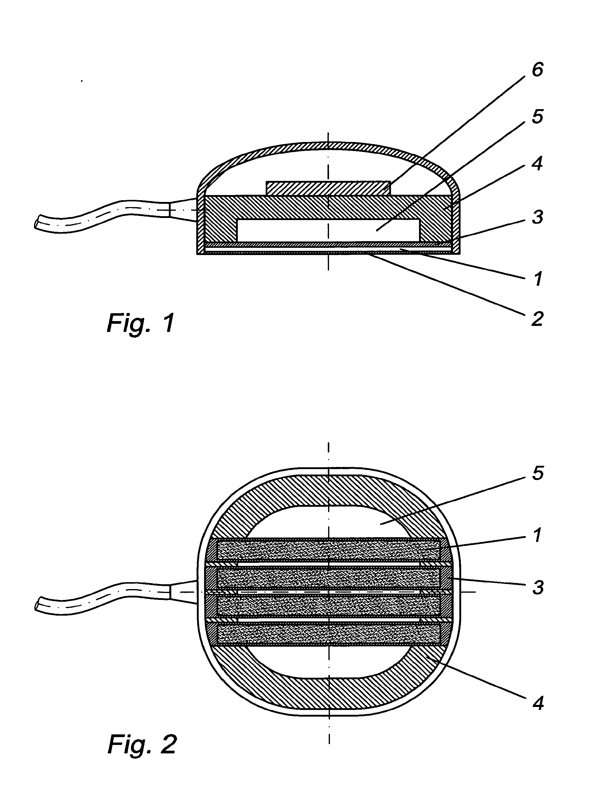
[0037]FIG. 1 illustrates a sensor based element 4 in a cross sectional view, wherein the sensor base element is configured as a rigid support circuit board on which the electronic amplifier 6 (charge amplifier) is directly soldered in order to prevent charge losses. The measurement membrane laminate includes a flexible polyimide conductor plate 3, plural parallel metal coated PVDF-foils 1 and a polyimide protective foil 2 and is glued on the sensor base element 4, so that a cavity 5 is created between the measurement membrane laminate the sensor base element 4, wherein the cavity can be produced e.g. through milling the sensor base element-support circuit board 4 and so that the measurement membrane laminate is tension preloaded in a direction of the piezo polarization of the PVDF-foil strips 1. The amplifier electronics 6, the sensor base element support circuit board 4, the polyimide circuit board 3 and the metal side of the PVDF-foil strips 1 are connected in an electrically cond...


PUM


Abstract

The invention relates to a piezoelectric sensor for the improved measurement of mechanical variables such as force, pressure or measurement variables which are derived there from, particularly a PVDF film sensor having an improved sensitivity and temperature stability of the measurement signal for pressure measurements that vary in time and/or space, and for the one- and two-dimensional determination of the position and propagation velocity of pressure fluctuations and pressure waves with a single measurement sensor at a measurement location. A preferred field of application of the invention is the non-invasive, low strain and continuous measurement of the pulse rate and the systolic and diastolic blood pressure of humans and animals by determining the velocity and the signal form of the pulse waves. The object of the invention is to allow the measurements of the blood pressure and the pulse rate, for example even in the case of emergency patients having only a very low blood pressure and patients having circulatory disorders in the extremities, for example patients which have developed diabetes or the “smoker's leg”, by using only one sensor at a measurement location due to the improved measurement sensitivity of the piezoelectric sensor, with the result that the continuous application of a pressurized jacket for continuously measuring and monitoring the blood pressure is not necessary. The present invention solves this problem in that a plurality of parallel strips of a piezoelectric material (1) are associated as a measurement membrane in the pressure sensor according to the invention with a sensor base body (4) in such a manner that the parallel strips are tension preloaded in a one-dimensional and elastic manner in the direction of the piezo dipole orientation and that an empty cavity (5) is provided between the tension preloaded piezoelectric sensor material (1) in the measurement portion and the sensor base body (4), formed by a recess/cutout.

Description

CROSS REFERENCE TO RELATED APPLICATIONS[0001]This application is a national stage of PCT International application no. PCT / EP2009 / 005543 filed Jul. 17, 2009, which claims priority to German application Ser. No. 10 2008 024 737.5 filed May 20, 2008.BACKGROUND OF THE INVENTION[0002]The invention relates to a piezoelectric sensor according to the preamble of patent claim 1 for an improved measurement of mechanical variables such as force, pressure or measurement variables which are derived there from, particularly a PVDF film sensor exhibiting an improved sensitivity and temperature stability of the measurement signal for measuring pressures that vary in time and / or space, and for the one- and two-dimensional determination of a position and propagation velocity of pressure fluctuations and pressure waves. A preferred field of application for the invention is a non-invasive, low impact and continuous measurement of a pulse rate and a systolic and diastolic blood pressure of humans and a...

Claims


Application Information

Patent Timeline
Patent Type & Authority Applications(United States)
IPC IPC(8): A61B5/021
CPCA61B5/021A61B5/02125A61B2562/043A61B2562/0247A61B5/0285A61B5/02A61B5/02035A61B5/02116A61B5/022A61B5/024A61B5/026A61B5/03G01L9/008
Inventor KOPETSCH, ROLANDNASSERI, MOHAMMADBERGMANN, STEPHAN
Owner SECTORCON ING FUR SYST UND SOFTWARETECHN MBH
Why Eureka
Try Eureka