
Apparatus and method for distant bus extended system

Inactive Publication Date: 2011-07-07
ASPEED TECH
View PDF5 Cites 7 Cited by
  • Summary
  • Abstract
  • Description
  • Claims
  • Application Information

AI Technical Summary

Benefits of technology

[0007]One object of the invention is to provide a distant PCIe extended system that can reduce the production cost.
[0008]One object of the invention is to provide a distant PCIe extended system that can reduce the purchasing cost for consumers.
[0009]One object of the invention is to provide a distant PCIe extended system that can increase the transmission distance dramatically (over 100 m).
[0014]The distant bus extended method according to the embodiments of the invention utilize the signal converting circuit to convert the PCIe interface signal into a data packet and then transfer the data packet through the transmission medium via the PVD PHY layer. Therefore, the distant bus extended method according to the embodiments of the invention can accommodate long-distance, over 100 meters, data transmission through a twisted pair cable or an optical fiber line. Besides, the PVD PHY layer can be implemented by existing commonly available devices that are provided with the physical layer circuit. Thus, the existing commonly available a twisted pair cable or an optical fiber line can be utilized as the transmission medium for such data transmission. In conclusion, by way of the above mentioned approaches, the distant PCIe extended system and the method according to the embodiments of the invention can greatly reduce the design expense and the production cost while better transmission efficiency compared to the prior technique can be achieved.

Problems solved by technology

Currently, the distance for bus of a general computer peripheral component interconnect express (PCI Express, hereinafter abbreviated as: PCIe) interface is limited and, therefore, such bus can only be used for a short distance.
However, using the transmission line consistent with the PCI Express External Cabling specification to transmit data causes the problem of increasing cost dramatically and the distance still limited to 20-30 m.

Method used


Image

  • Apparatus and method for distant bus extended system
  • Apparatus and method for distant bus extended system
  • Apparatus and method for distant bus extended system

Examples


Embodiment Construction

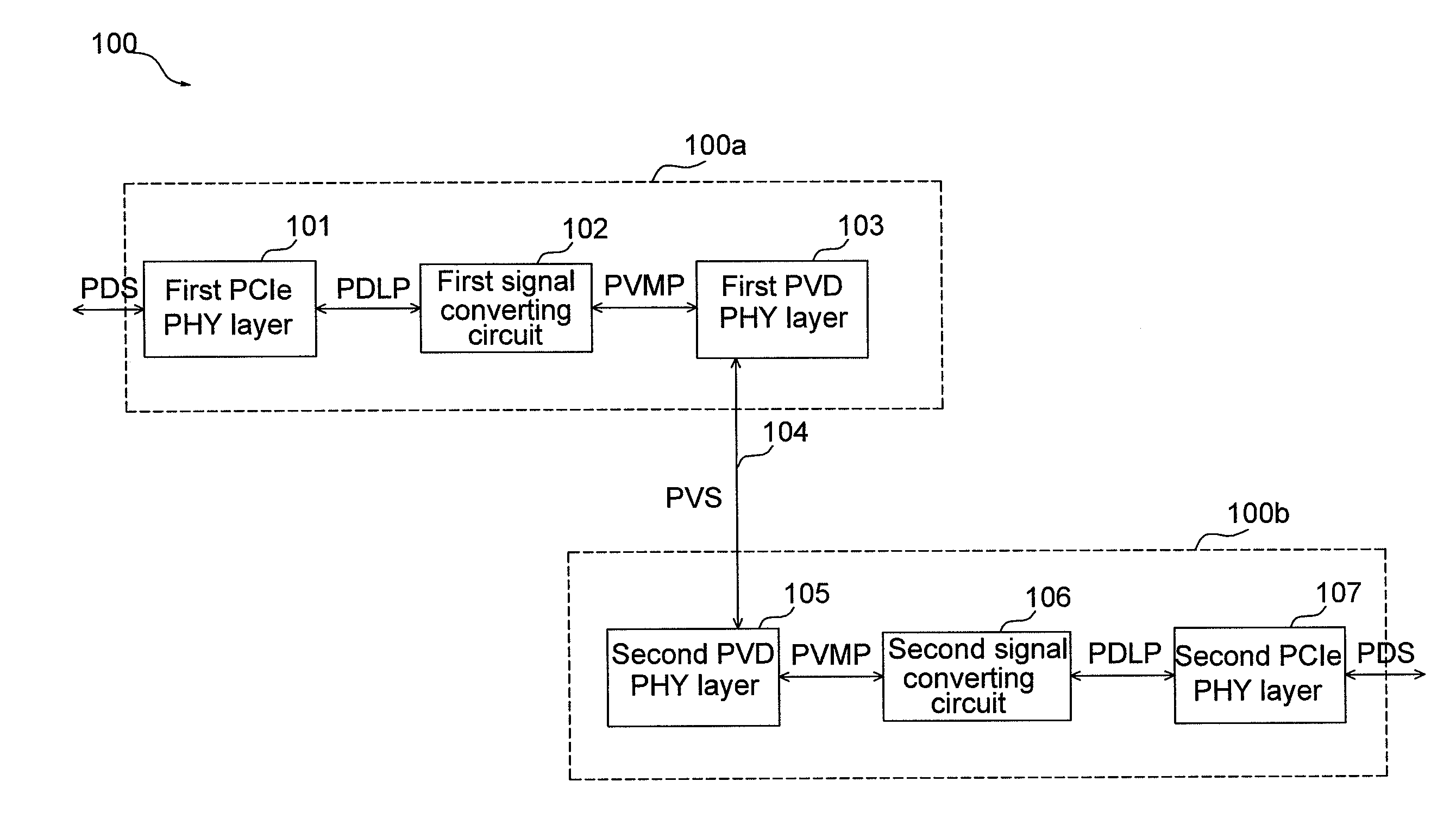
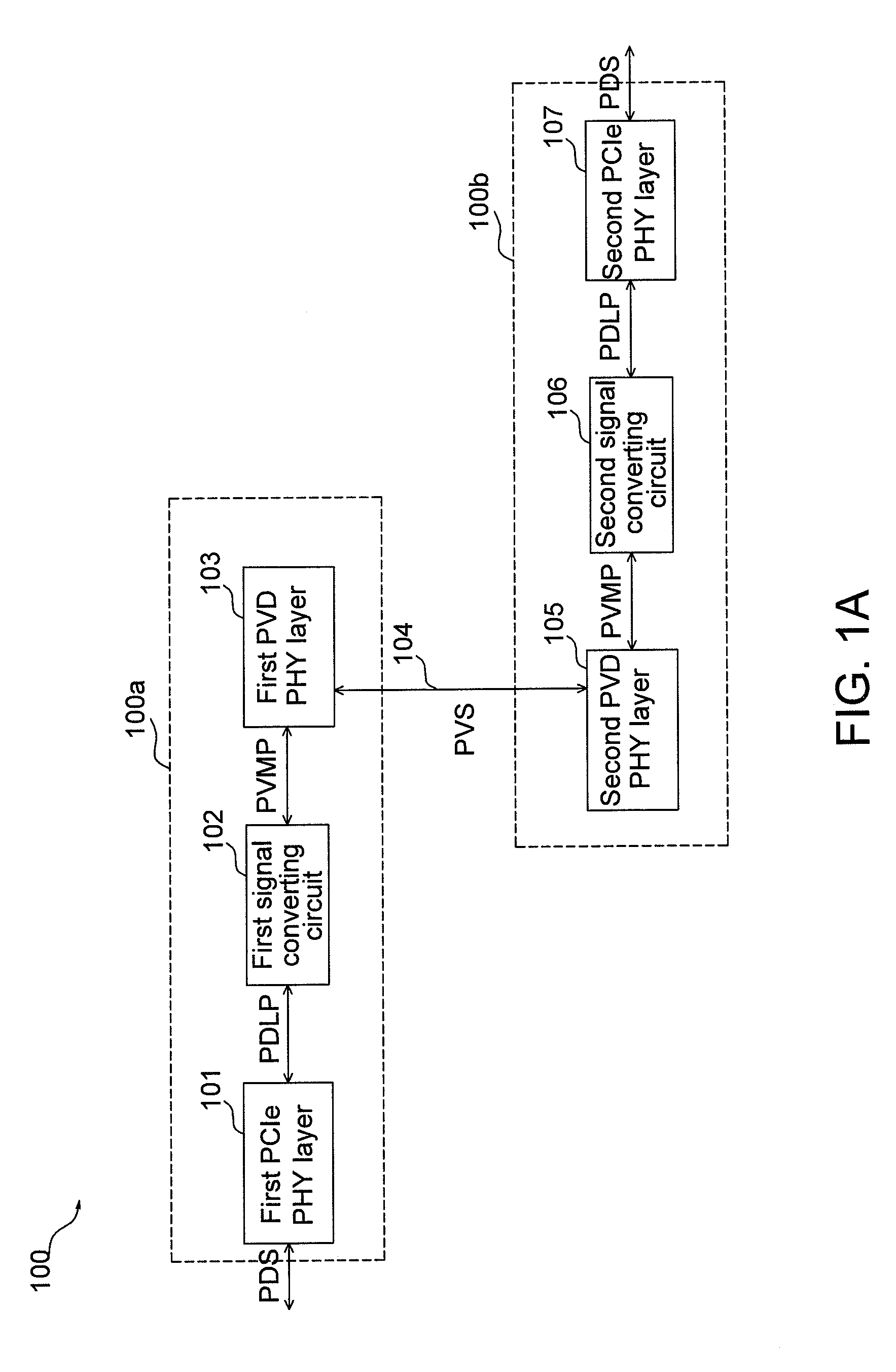
[0042]FIG. 1A shows schematic diagrams illustrating the distant PCIe extended system according to one embodiment of the invention. A distant PCIe extended system 100 includes a local PVD 100a, a transmission medium 104, and a remote PVD 100b. The local PVD 100a includes a first PCIe PHY layer 101, a first signal converting circuit 102, and a first PVD PHY layer 103. Correspondingly, the remote PVD 100b also includes a second PVD PHY layer 105, a second signal converting circuit 106, and a second PCIe PHY layer 107.

[0043]The first PCIe PHY layer 101 is used for transferring at least a PCIe physical signal PDS.

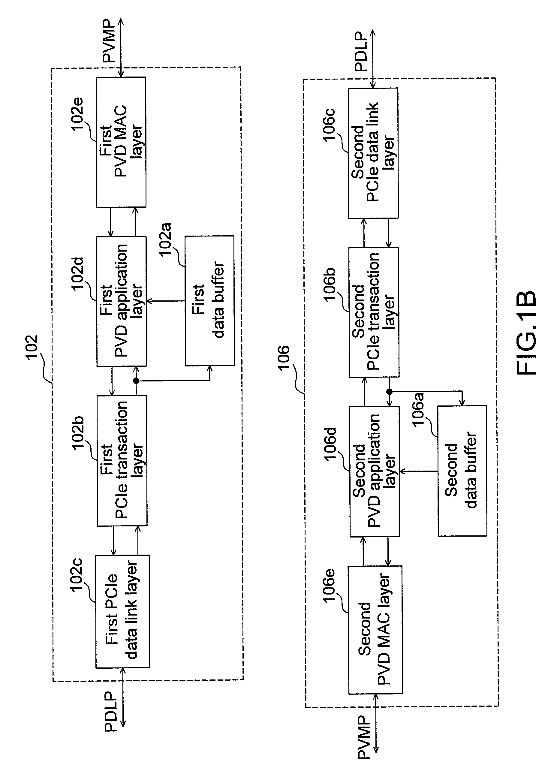
[0044]The signal converting circuit 102 is coupled to the first PCIe PHY layer 101 and used to convert the PCIe physical signal PDS into at least a PVD MAC packet PVMP. The PVD MAC packet PVMP according to one embodiment of the invention may be a network packet or a packet that does not include the internet protocol (IP). The PVD MAC packet PVMP according to another embodiment o...


PUM


Abstract

The invention discloses a distant PCIe extended system. The distant PCIe extended system includes a local PCIe virtualization device (PVD), at least a transmission medium and at least a remote PVD. The PVD includes a PCIe PHY layer, a signal converting circuit, at least a PVD PHY layer and a transmission medium. The PCIe PHY layer is used to receive a PCIe physical signal. The signal converting circuit is coupled to the PCIe PHY layer and used to convert the PCIe data link layer packet into at least a PVD MAC packet. The PVD PHY layer is coupled to the signal converting circuit and used to process and transfer the PVD MAC packet. The transmission medium receives and transfers the PVD physical signal.

Description

CROSS-REFERENCE TO RELATED APPLICATIONS[0001]This application is a Continuation-in-Part of co-pending application Ser. No. 12 / 203,007, filed on Sep. 2, 2008, and for which priority is claimed under 35 U.S.C. §120, the entire contents of which are hereby incorporated by reference.BACKGROUND OF THE INVENTION[0002](a) Field of the Invention[0003]The present invention relates to a bus extended computer system architecture, and particularly to a long-distant computer peripheral component interconnect express (PCIe) extended bus system.[0004](b) Description of the Related Art[0005]Currently, the distance for bus of a general computer peripheral component interconnect express (PCI Express, hereinafter abbreviated as: PCIe) interface is limited and, therefore, such bus can only be used for a short distance. To resolve the distance limitation problem of signal transmission by PCIe, a PCI Express External Cabling specification has been proposed in other technical fields to increase the signal...

Claims


Application Information

Patent Timeline
IPC IPC(8): G06F13/20
CPCG06F13/385
Inventor LIN, HUNG-MINGHUANG, HUNG-JUYUAN, JEN-MINBAI, MING-CHI
Owner ASPEED TECH
Learn More