
Waterless humidifier for residential and commercial furnaces

Active Publication Date: 2011-07-14
GAS TECH INST
View PDF26 Cites 7 Cited by
  • Summary
  • Abstract
  • Description
  • Claims
  • Application Information

AI Technical Summary

Benefits of technology

[0009]Accordingly, it is one object of this invention to provide a method and apparatus for humidifying habitable space air which substantially eliminates the necessity of a water supply required by conventional residential and commercial humidification systems and methods.
[0011]It is yet another object of this invention to reduce the amount of energy required for humidification of habitable spaces compared with conventional humidification equipment and methods, in particular, by eliminating the energy employed for the direct evaporation of water used by conventional humidification and methods.
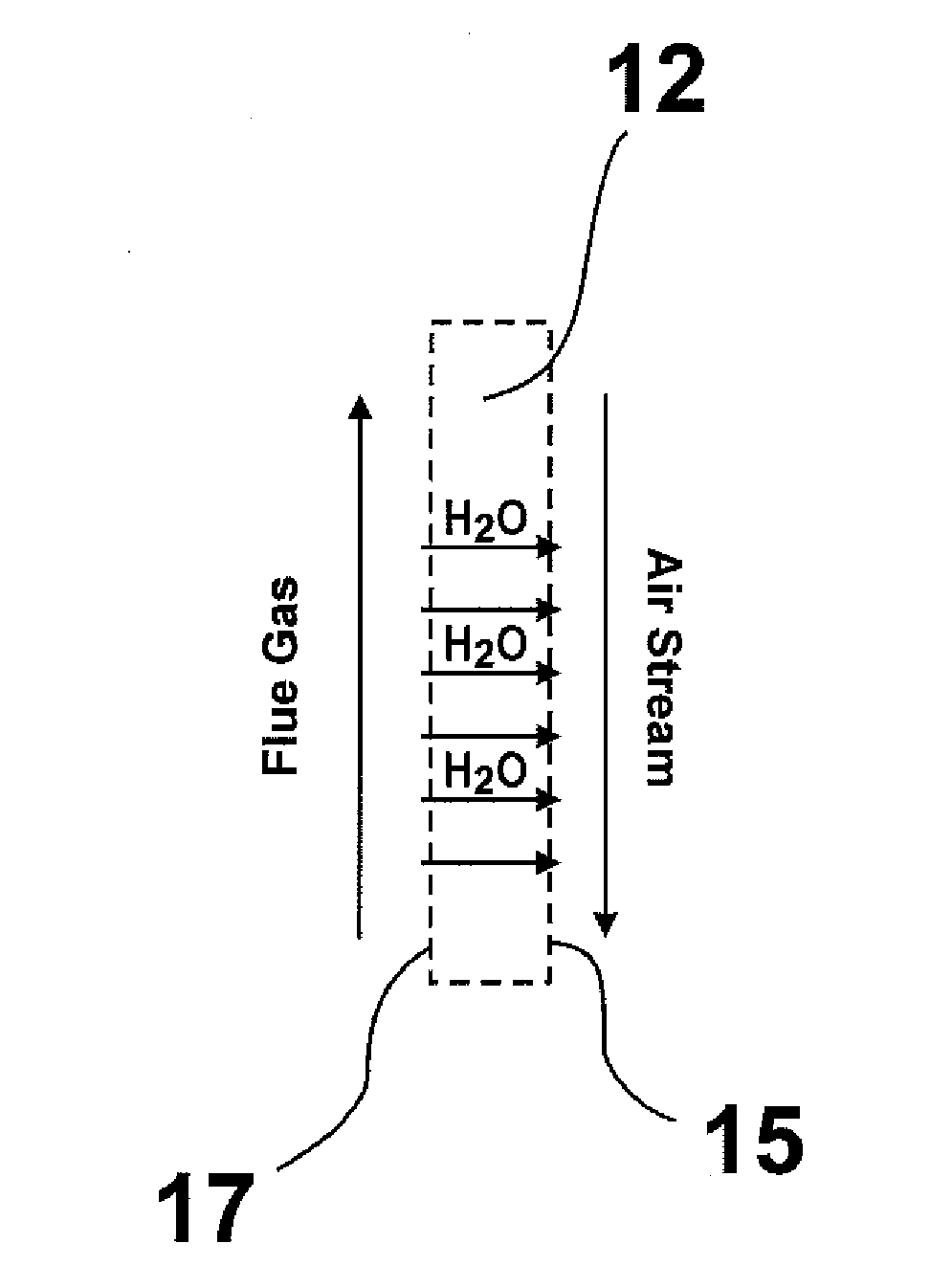
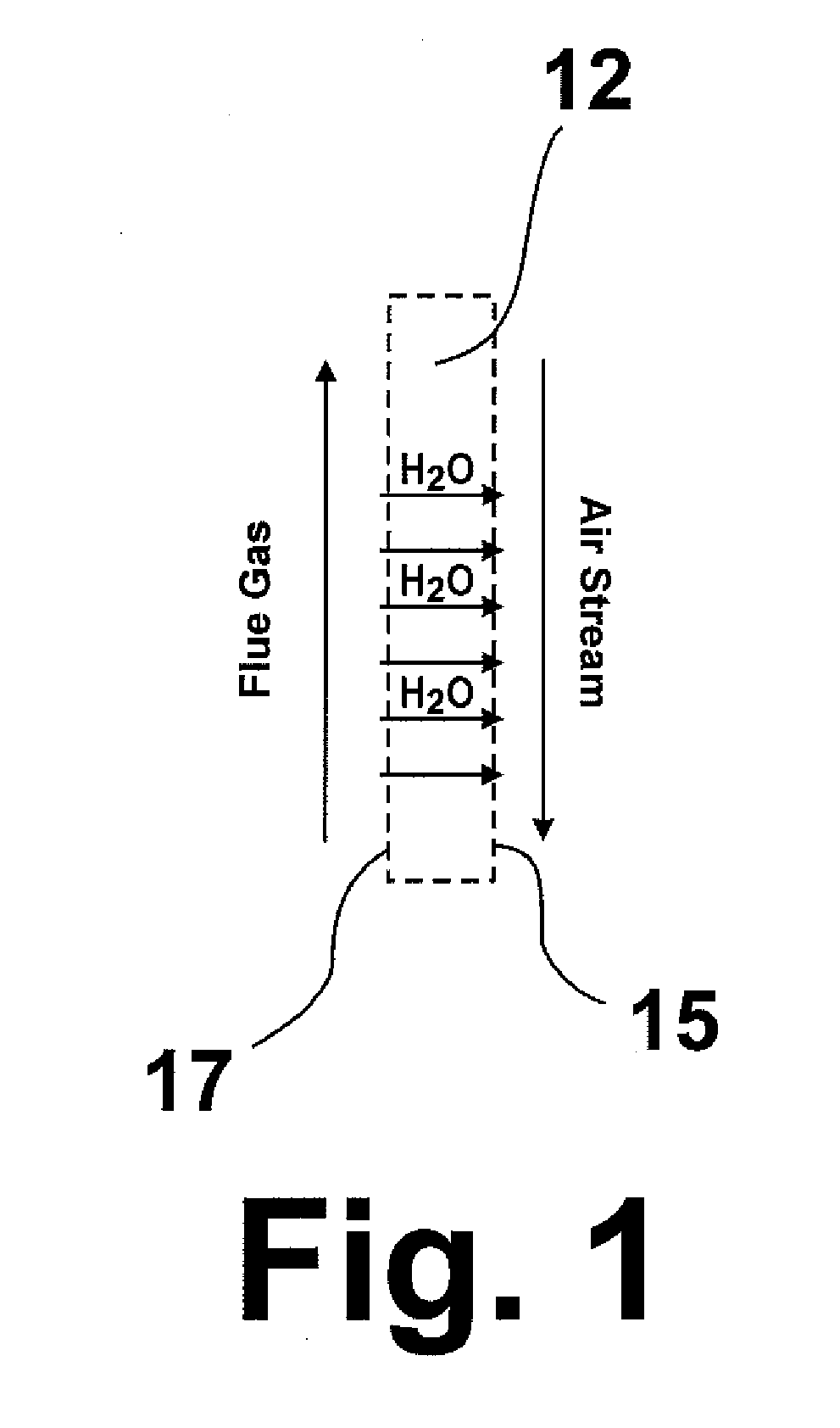
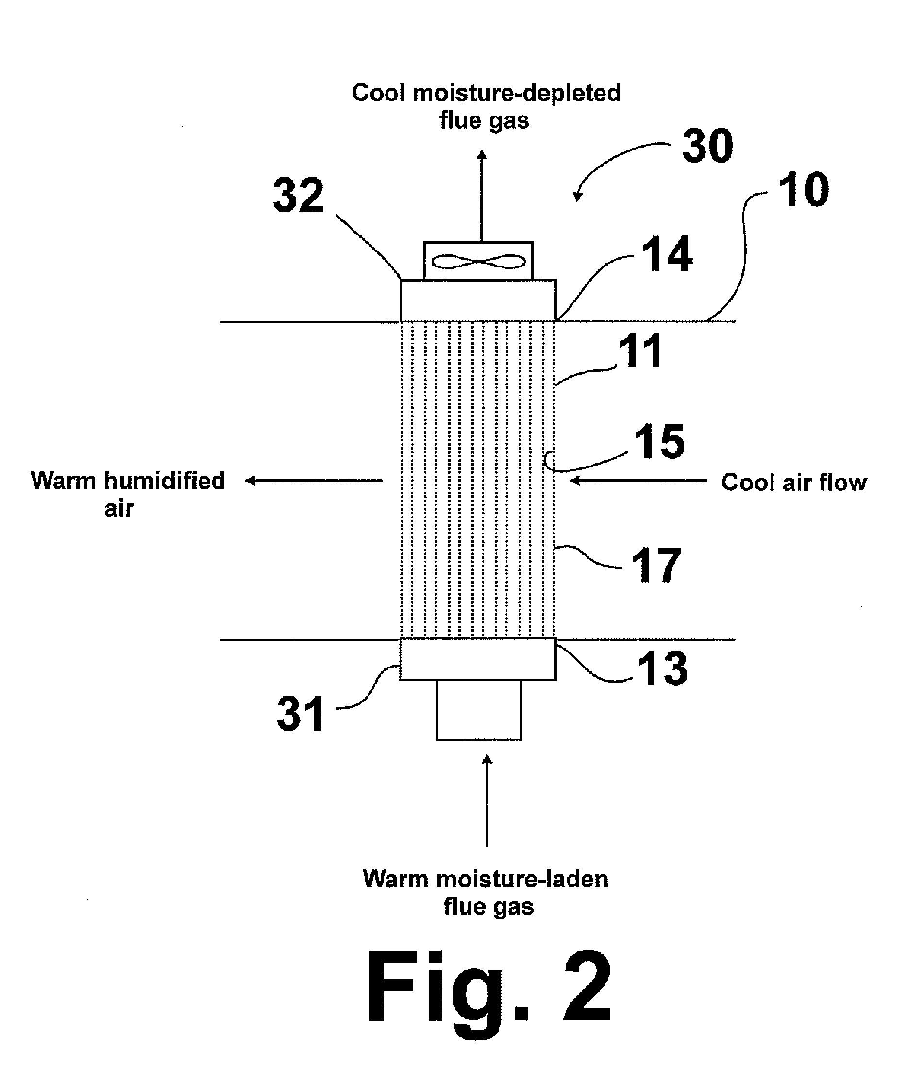
[0012]These and other objects of this invention are addressed by a method for humidifying air in habitable spaces or rooms in residential or commercial buildings in which a flue gas comprising water vapor generated by a residential or commercial furnace through the reaction of fuel with combustion air is provided to one side of a porous liquid water transport membrane and air, referred to herein as habitable space air or room air, to be humidified, typically at a temperature in the range of about 40° F. to about 100° F., preferably in the range of about 60° F. to about 80° F., is provided to the opposite side of the porous liquid water transport membrane in an amount sufficient to provide an air to flue gas volume flow rate ratio of at least 8.3:1. At least a portion of the water vapor is condensed in the pores of the membrane, producing liquid water in a sufficient amount to prevent other flue gas components from passing through the membrane, which liquid water is transported through the membrane to the opposite side of the membrane where it is evaporated into the air to be humidified, producing humidified habitable space air which is then provided to the habitable space. By using this membrane separation technique to transfer water vapor from the flue gases to the habitable space air, harmful gaseous components in the flue gas, such as CO, CO2, and N2, are substantially blocked from passing through the membrane due to the presence of the liquid water in the membrane, thereby preventing contamination of the humidified habitable space air. In addition to humidifying the air, the higher temperature flue gas also gives up its heat to the lower temperature habitable space air, thereby enabling capture of the energy from the flue gas and increasing efficiency of the air heating and humidification process. Because only substantially pure water passes through the membrane, water contaminant problems associated with the operation of conventional building humidifiers over an extended period of time are avoided. In addition, use of the water vapor in the flue gas in accordance with the method and apparatus of this invention avoids the cost of installing a water supply line and the cost to regularly replace the filter employed in conventional systems due to mineral deposition build up and microbial growth on the filter. The driving force for this transfer of heat and mass is the differential partial pressure of the condensable water vapor across the membrane.

Problems solved by technology

However, flue gas typically contains contaminants, such as carbon monoxide (CO), carbon dioxide (CO2), and nitrogen (N2), which would contaminate the building air supply, rendering the building uninhabitable.

Method used


Image

  • Waterless humidifier for residential and commercial furnaces
  • Waterless humidifier for residential and commercial furnaces
  • Waterless humidifier for residential and commercial furnaces

Examples


Embodiment Construction

[0019]The invention disclosed herein is a method and apparatus or system for environmentally conditioning spaces or rooms within buildings employing a transport membrane humidifier in which water vapor contained within a flue gas is transferred to the air in the spaces, thereby humidifying the air while blocking undesirable gaseous components in the flue gas from passing into the air, and in which the water vapor in the flue gas is the sole source for water used to humidify the air. The driving force for the water vapor to pass through the membrane is the water vapor partial pressure difference between the flue gas and the air to be humidified. That is, the water vapor partial pressure on the flue gas side of the membrane of the transport membrane humidifier is higher than the water vapor partial pressure on the air side of the membrane. The method and apparatus of this invention avoid the use of energy directly for water vaporization as required by traditional home and building hum...


PUM


Abstract

A method and apparatus for humidifying residential and commercial buildings in which a flue gas generated by a residential or commercial furnace is provided to one side of a porous liquid water transport membrane and habitable space air is provided to an opposite side of the porous liquid water transport membrane in an amount sufficient to provide a habitable space air to flue gas volume flow rate ratio of at least 8.3:1. At least a portion of the water vapor in the flue gas is condensed, providing condensed liquid water which is passed through the porous liquid water transport membrane to the habitable space air side of the porous liquid water transport membrane. On the habitable space air side of the membrane, the condensed liquid water is evaporated into the habitable space air, producing humidified habitable space air which is provided to the rooms of the residential and commercial buildings. Beneficially, no supplemental water source is required for the humidification process.

Description

CROSS-REFERENCE TO RELATED APPLICATION[0001]This application is a continuation-in-part application of our co-pending U.S. patent application Ser. No. 12 / 033,314, filed 19 Feb. 2008.BACKGROUND OF THE INVENTION[0002]1. Field of the Invention[0003]This invention relates to a method and apparatus for humidifying air in habitable spaces using the water vapor from moisture-laden flue gas produced by residential or commercial furnaces. In one aspect, this invention relates to a “waterless humidification” method and apparatus for residential and commercial buildings. By “waterless humidification,” we mean humidification without the addition of supplemental water, i.e., without any water other than the water obtainable from moisture-laden flue gas. In one aspect, this invention relates to a method and apparatus for humidifying air using a liquid water transport membrane in which water vapor from the moisture-laden flue gas is condensed and the condensed (liquid) water is transported through ...

Claims


Application Information

Patent Timeline
IPC IPC(8): F24F3/14
CPCF24F2003/1435Y02E20/363B01D53/268F23J15/06F24F6/02B01D53/266F23J15/00F24D5/04F23L2900/00001Y02E20/30
Inventor WANG, DEXINLISS, WILLIAM E.KNIGHT, RICHARD A.
Owner GAS TECH INST
Learn More