Head for thermal assisted magnetic recording device, and thermal assisted magnetic recording device

a recording device and magnetic recording technology, applied in the field of thermal assisted magnetic recording devices, can solve the problems of reducing the efficiency increasing the power consumption inadvertently, and increasing the temperature of elements, so as to achieve the effect of reducing the temperature rise of optical near-field generating elements, reducing the power consumption, and improving the heat radiating performan

Inactive Publication Date: 2011-07-14
HITACHI LTD
View PDF20 Cites 92 Cited by
  • Summary
  • Abstract
  • Description
  • Claims
  • Application Information

AI Technical Summary

Benefits of technology

[0020]A layer constituted by a conductive material may be formed beside the main pole. Accordingly, heat radiating performance can be improved and a temperature rise of the element can be suppressed. In addition, the layer constituted by a conductive material formed beside the main pole may be brought into contact with the conductive structure that generates an optical near-field. Accordingly, since heat generated at the optical near-field generating element is directly transferred to the layer constituted by a conductive material formed beside the main pole, a temperature rise of the optical near-field generating element can be further reduced.
[0021]An end of the core may be inclined at a termination of the waveguide. If not inclined, light is reflected at a boundary between the core and air on the slider air-bearing surface and light ends up returning in a direction of an entrance to the waveguide. A part of the returned light is further reflected at the entrance of the waveguide and advances toward an exit of the waveguide. The returned lights interfere with each other inside the waveguide and cause a fluctuation of optical power inside the waveguide. In addition, a part of the light reflected at a boundary between the core and air returns to the semiconductor laser. An output intensity of the semiconductor laser fluctuates due to the returned light. By inclining the termination of the waveguide, the reflected light at the termination no longer returns to the entrance-side of the waveguide and fluctuation of optical power is reduced. Furthermore, by setting an angle of the core termination to within an appropriate range, generated optical near-field intensity can be reinforced. To this end, the angle of the core termination is favorably set to 60 degrees or less if the core termination not inclined is assumed to have an angle of 0 degrees.
[0022]A light blocking film may be formed at the termination of the waveguide in order to prevent light outputted from the termination of the waveguide from irradiating a medium as background light.
[0023]The width of the waveguide may be set to a width that enables the waveguide to become a multi-mode waveguide. Accordingly, a coupling

Problems solved by technology

With thermally assisted magnetic recording, since a semiconductor laser must be driven in addition to a magnetic head, power consumption inadvertently increases by just that much.
In addition, light irradiated on the optical near-field generating element is absorbed by the optical near-field generating element and causes a rise in the temperature of the element.
Th

Method used


Image

  • Head for thermal assisted magnetic recording device, and thermal assisted magnetic recording device
  • Head for thermal assisted magnetic recording device, and thermal assisted magnetic recording device
  • Head for thermal assisted magnetic recording device, and thermal assisted magnetic recording device

Examples


Embodiment Construction

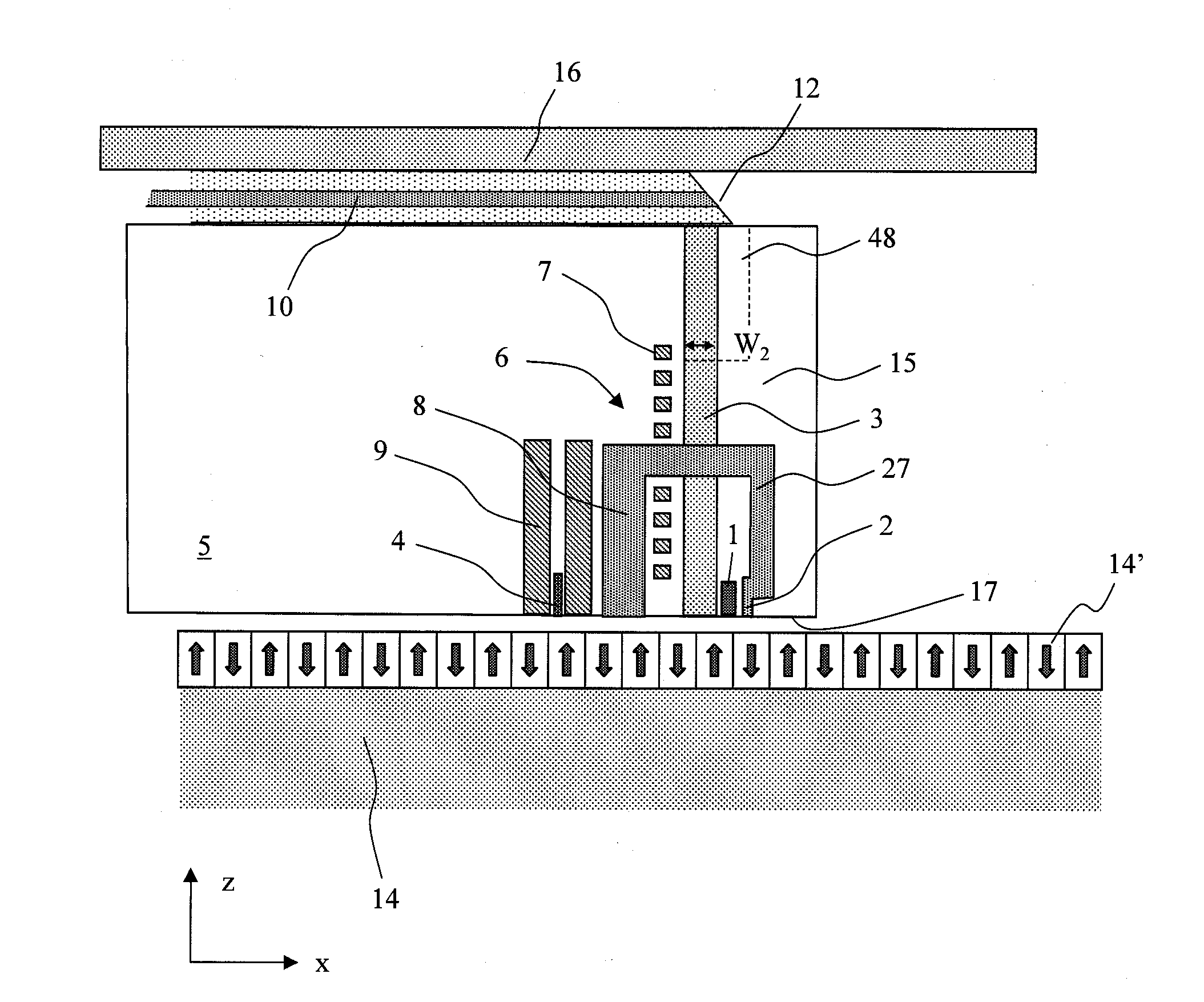
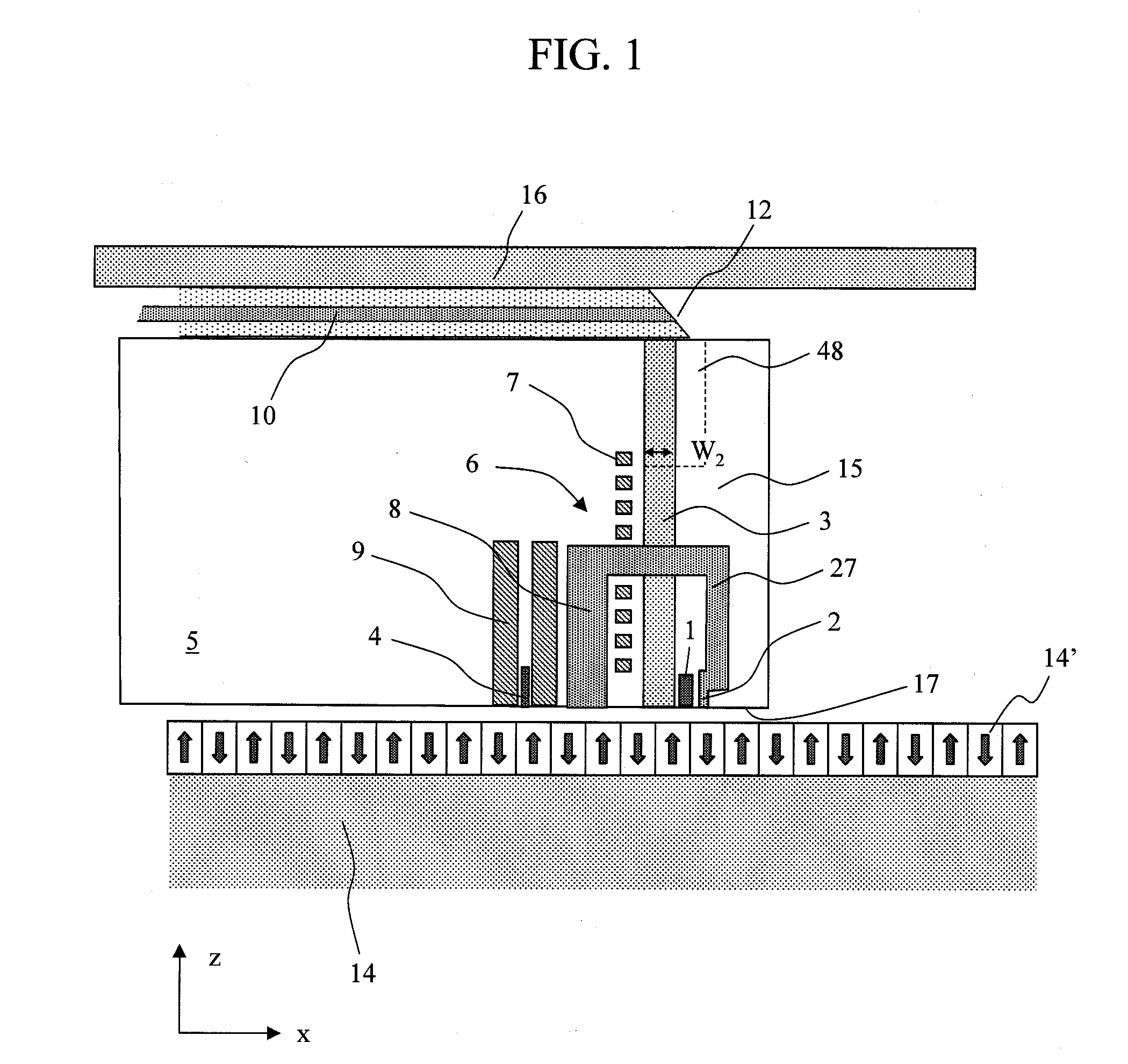
[0144]Hereinafter, an embodiment of the present invention will be described with reference to the drawings. In the following drawings, an x direction denotes a track direction, a y direction denotes a track width direction, and a z direction denotes a direction perpendicular to a air-bearing surface. In addition, an example in which a conductive structure is made of metal will be used in the following description.

[0145]FIG. 1 is a schematic cross-sectional view illustrating a configuration example of a magnetic head according to the present invention. The magnetic head according to the present invention includes a thermally assisted magnetic recording head and a reproducing head. The thermally assisted magnetic recording head includes a recording magnetic field generating unit and an optical near-field generating unit. A recording magnetic field is generated by a magnetic head unit 6 made up of a coil 7, a fat magnetic pole 27 for transmitting flux generated at the coil, a main pole...


PUM


Abstract

An optical near-field generating efficiency of an optical near-field generating element is improved and a temperature rise of the element is suppressed. An optical near-field is generated using a conductive structure having a cross-sectional shape whose width in a direction perpendicular to a polarization direction of incident light transmitted through a waveguide gradually becomes shorter toward a vertex where an optical near-field is generated and having a shape whose width gradually, or in stages, becomes smaller in a traveling direction of the incident light toward the vertex where an optical near-field is generated. The waveguide is arranged beside the conductive structure and an optical near-field is generated via a surface plasmon generated on a lateral face of the conductive structure.

Description

CROSS-REFERENCE TO RELATED APPLICATION[0001]This application is related to U.S. application Ser. No. 12 / 903,276 filed on Oct. 13, 2010, the disclosure of which is hereby incorporated by reference into this application.CLAIM OF PRIORITY[0002]The present application claims priority from Japanese patent application JP 2010-006205 filed on Jan. 14, 2010, the content of which is hereby incorporated by reference into this application.BACKGROUND OF THE INVENTION[0003]1. Field of the Invention[0004]The present invention relates to a thermally assisted magnetic recording head including an optical near-field generator and a magnetic recording device using the thermally assisted magnetic recording head.[0005]2. Background Art[0006]A thermally assisted magnetic recording system has been recently proposed as a recording system that realizes a recording density of 1 Tb / in2 or higher (H. Saga, H. Nemoto, H. Sukeda, and M. Takahashi, Jpn. J. Appl. Phys. 38, Part 1, 1839 (1999)). With a conventional...

Claims


Application Information

Patent Timeline
IPC IPC(8): G11B11/00
CPCG11B5/1278G11B5/3116G11B2005/0021G11B5/6088G11B2005/0005G11B5/314
Inventor MATSUMOTO, TAKUYA
Owner HITACHI LTD
Why Eureka
Try Eureka