Coated hole cutter

a hole cutter and coating technology, applied in the field of hole cutters, can solve the problems of increasing the cost of the hole cutter to consumers, increasing the manufacturing cost, and requiring a relative large amount of coating material to coat the cutter, so as to reduce interfere with the cutting efficiency of the hole cutter

Active Publication Date: 2011-07-14
BLACK & DECKER INC
View PDF38 Cites 41 Cited by
  • Summary
  • Abstract
  • Description
  • Claims
  • Application Information

AI Technical Summary

Benefits of technology

[0015]One advantage of the hole cutters of the present invention is that because the coating is only applied to the external surface of the blade body, but not to the cutting edge or to the interior of the hole cutter, there is no opportunity for a coating on these surfaces to become heated and mixed with the chips or dust, or to otherwise interfere with the cutting efficiency of the hole cutter. Another advantage of some currently preferred embodiments of the hole cutters of the present invention is that because the coating is an ink as opposed to a paint or other typical prior art coating, even if the coating were to become excessively heated (which is not likely as the coating is not applied at the high heat interfaces with the work piece), it does not become soft or gooey and therefore does not reduce the cutting efficiency of the hole cutter. Yet another advantage of the hole cutters of the present invention is that since the coating is applied to the external surface of the cylindrical blade body, the coating allows the hole cutter to bear a desired color, such as the manufacturer's distinctive color or trade dress, and to bear trademarks, logos, information identifying the manufacturer or seller, part numbers, and / or other desired information. Yet another advantage of the hole cutters of the present invention is that the appearance of the dark colored cutting edge against the contrasting color of the coating on the blade body provides an aesthetically desirable appearance. A further advantage of the currently preferred embodiments of the present invention is that the non-metallic colored coating is applied only in a band to the exterior surface of the cylindrical blade body, and therefore less colored coating may be required and / or the application of the coating to the cutting edge can be less expensive in comparison to prior art hole cutters that have coatings, such as paints, applied to the external and internal surfaces of the hole cutter and / or to all surfaces of the hole cutter.

Problems solved by technology

One of the drawbacks encountered with some prior art hole cutters is that the coating is applied to all surfaces of the hole cutters, including all exterior and interior surfaces of the hole cutters, and therefore a relatively large amount of coating material is needed to coat the cutters.
Since coating materials can be costly, these coating techniques can increase the manufacturing costs and, ultimately, increase the costs of the hole cutters to consumers.
Another drawback encountered with prior art hole cutters is that the interfaces of the blades bodies and work pieces, such at the cutting edges and the interior and exterior surfaces of the blade bodies adjacent to the cutting edges, can become heated due to the frictional forces between the rotating blade bodies and work pieces.
The thermal energy created by such frictional forces gives rise to substantial heat that can soften or otherwise turn the coatings on these areas soft or gooey.
Soft or gooey coatings act to increase frictional forces at the interfaces, and thereby reduce overall cutting speed and degrade the cutting efficiency of the hole cutters.
A soft or gooey coating on the interior of a hole cutter can interfere with removal of a slug located therein, as a soft or gooey coating can stick to a slug and increase the frictional forces between the slug and the interior surface of the hole cutter to prevent the slug from being pushed or pried out of the interior of the cutter.
Still further, the soft or gooey coatings can transfer from the hole cutters to work pieces, thereby staining, marking or otherwise tarnishing the work pieces.
Another drawback encountered with some prior art hole cutters is that they are unable to evacuate the volume of chips and / or dust created during cutting.
The thermal energy created by such frictional forces gives rise to substantial heat that can turn the coatings on the hole cutters soft or gooey.
The soft or gooey coatings tend to trap dust and chips at the interfaces of the hole cutters and work pieces, such as at the cutting edge, and further degrade the cutting efficiency of the hole cutters.

Method used


Image

  • Coated hole cutter
  • Coated hole cutter
  • Coated hole cutter

Examples


Embodiment Construction

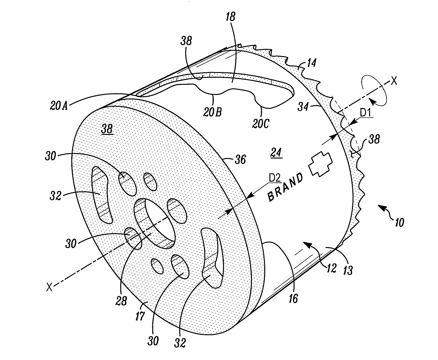
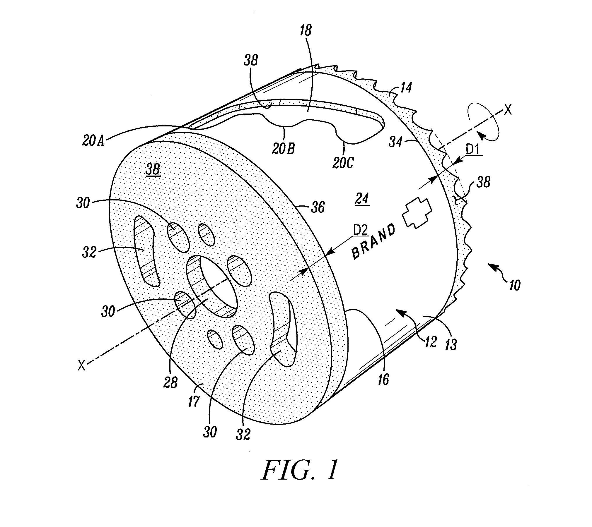
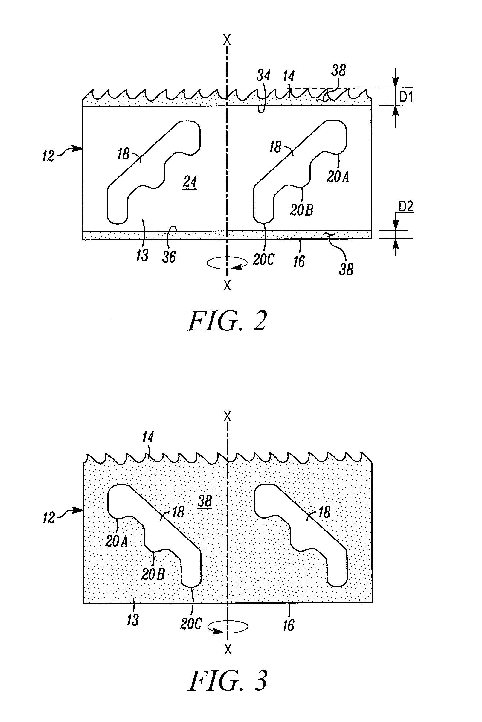
[0022]In FIG. 1, a hole cutter embodying the present invention is indicated generally by the reference numeral 10. The term “hole cutter” is used herein to mean a tool that cuts holes in work pieces, such as wood or metal work pieces, and includes without limitation hole saws. The hole cutter 10 includes a blade body 12 defining a side wall 13. The blade body 12 is shown in FIGS. 2 and 3 in its flattened state; however, as shown in FIG. 1, the blade body 12 is rolled or otherwise formed into a substantially cylindrical shape to form the hole cutter 10. As shown in FIG. 1, the side wall 13 extends around an axis of rotation “X” of the hole cutter 10 to define the substantially cylindrical blade body 12. One end of the blade body 12 is provided with a cutting edge 14 oriented substantially perpendicular to the axis of rotation X, and the opposing end of the blade body defines a rim 16. As shown in FIGS. 1 and 3, a cap 17 is fixedly secured, such as by welding, to the rim 16 to enclose...


PUM

PropertyMeasurementUnit
thickaaaaaaaaaa
temperatureaaaaaaaaaa

Abstract

A coated hole cutter including an ink-based colored coating applied only to the external surface of the cylindrical blade body of the hole cutter, but not to the surfaces of a circumferentially-extending cutting edge or to the interior surface of the blade body. The ink-based color coating is an ultraviolet activated ink that cures when the coating is exposed to a specific ultraviolet light intensity and wavelength. At least the surfaces of the cutting edge and the internal surface of the blade body, which do not include the coating, have a steam tempered oxide finish that imparts a color that contrasts with the color imparted by the coating.

Description

FIELD OF THE INVENTION[0001]The present invention relates to hole cutters, and more particularly, to hole cutters with coatings thereon.BACKGROUND INFORMATION[0002]A typical prior art hole cutter, or hole saw, includes a cylindrical blade body defining a plurality of saw teeth on the cutting edge of the blade body, and a plurality of apertures that are angularly spaced relative to each other about the blade body within an intermediate portion of the blade body. The apertures may define any of a variety of different configurations to facilitate inserting a tool into the apertures, such as a screw driver, to remove circular work piece slugs from within the interior of the blade body that result from cutting work pieces. The hole cutters are often coated, such as with paint, to protect the cutters against rust and / or for decorative or advertising purposes, such as with a particular manufacturer's distinctive color(s), trade dress, trademarks and / or logos.[0003]One of the drawbacks enco...

Claims


Application Information

Patent Timeline
Patent Type & Authority Applications(United States)
IPC IPC(8): B23B41/02
CPCB23B51/0406Y10T408/8957B23B2270/36B23B2228/10Y10T408/895B23B51/04B23B51/0467
Inventor ZIELONKA, ROBERT RICHARDDESANTIS, JOSEPH H.FITZGERALD, CHRISTOPHER F.WEREMCHUK, PETER
Owner BLACK & DECKER INC
Why Eureka
Try Eureka