Gear Assembly and Wind Turbine

a technology of gear assembly and wind turbine, which is applied in the direction of machines/engines, couplings, hoisting equipment, etc., can solve the problems of uneven wear of ring gears, and uneven wear of pinion gears, so as to reduce the maintenance effort, in particular of yaw drives, and increase production costs.

Inactive Publication Date: 2011-07-14
SIEMENS AG
View PDF11 Cites 23 Cited by
  • Summary
  • Abstract
  • Description
  • Claims
  • Application Information

AI Technical Summary

Benefits of technology

[0017]An inventive wind turbine comprises at least one inventive gear assembly. The gear assembly may, in particular, be part of the yaw drive of the wind turbine. An inventive wind turbine is advantageous in that the maintenance effort, in particular of the yaw drive, can be reduced with a moderate increase in costs for production of the gear assembly used in the yaw drive. Further advantageous result from the advantageous discussed with respect to the gear assembly.

Problems solved by technology

Hence, the pinion gears typically only mesh with a small fraction of the ring gear in most of time since large yawing angles which would require meshing with a substantial amount of the ring gear, are typically rare.
This leads to an uneven load distribution over the circumference of the ring gear.
As a consequence, those parts of the ring gear which experience more meshing with the pinion gear are worn more rapidly than the other parts of the ring gear and the wear of the ring gear is much more uneven than the wear of the pinion gears.
In particular this uneven wear of the ring gear is often the reason why the ring gear has to be replaced.
However, the ring gear is typically fixed to the wind turbine nacelle and is, therefore, difficult to replace.
Therefore, by applying an abrasion resistant coating only to the ring gear the life time of the part of the gear assembly which is the most difficult and the most expensive to replace can be increased while at the same time the number of parts which need to be coated with the abrasion resistant coating is small.

Method used


Image

  • Gear Assembly and Wind Turbine
  • Gear Assembly and Wind Turbine
  • Gear Assembly and Wind Turbine

Examples


Embodiment Construction

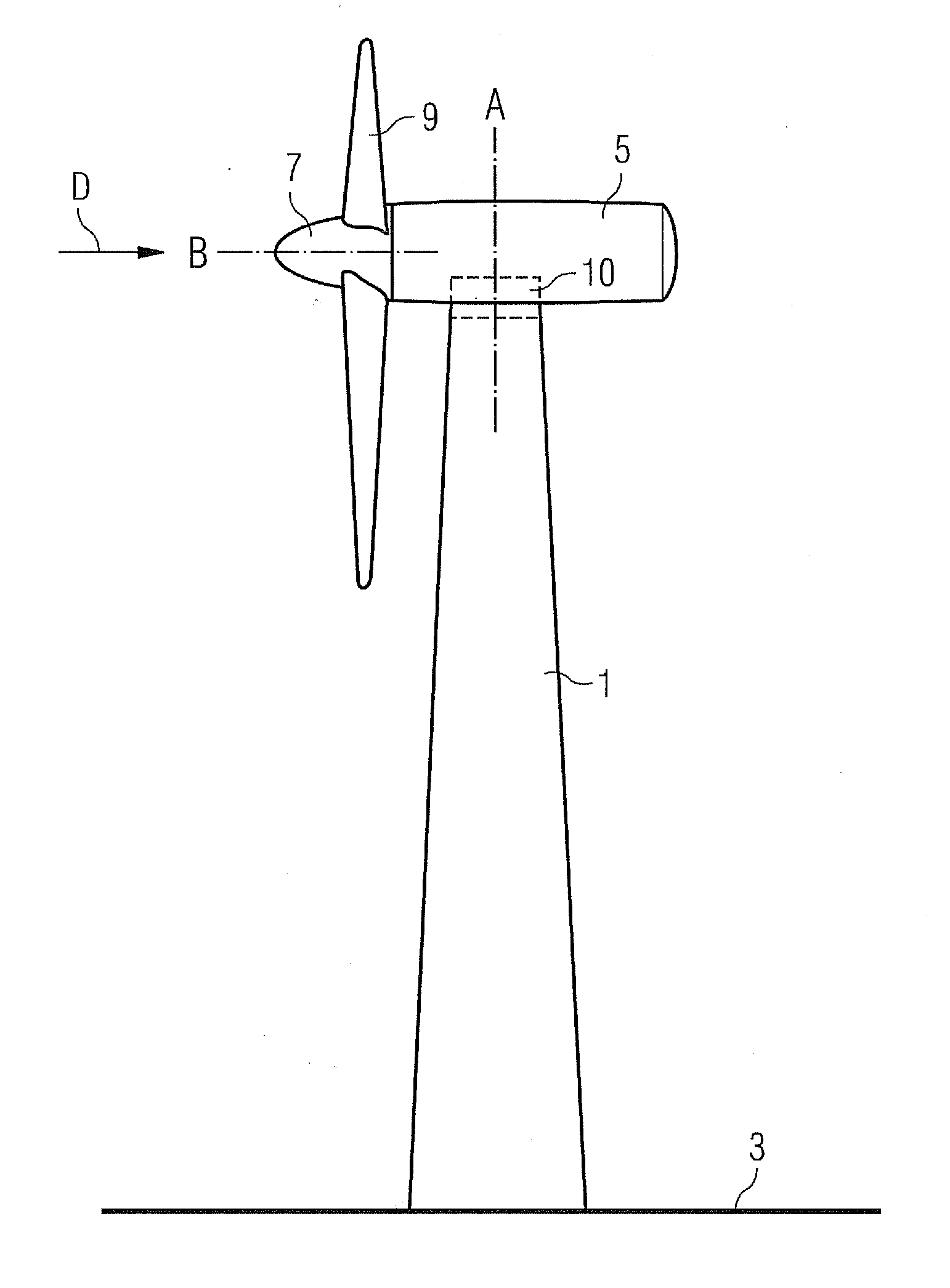
[0022]A typically wind turbine is shown in FIG. 1. The wind turbine 1 comprises a tower 1 which rests on a fundament in the ground 3. At the top of the tower 1, a nacelle 5 is located which carries a rotor 7 driven by the wind. Typically the rotor comprises three rotor blades 9 arranged in angles of 120°. However, other rotor designs with more or less than three rotor blades are possible, for example two bladed rotors or even one bladed rotors. However, two bladed rotors and, in particular, three bladed rotors are most commonly used.

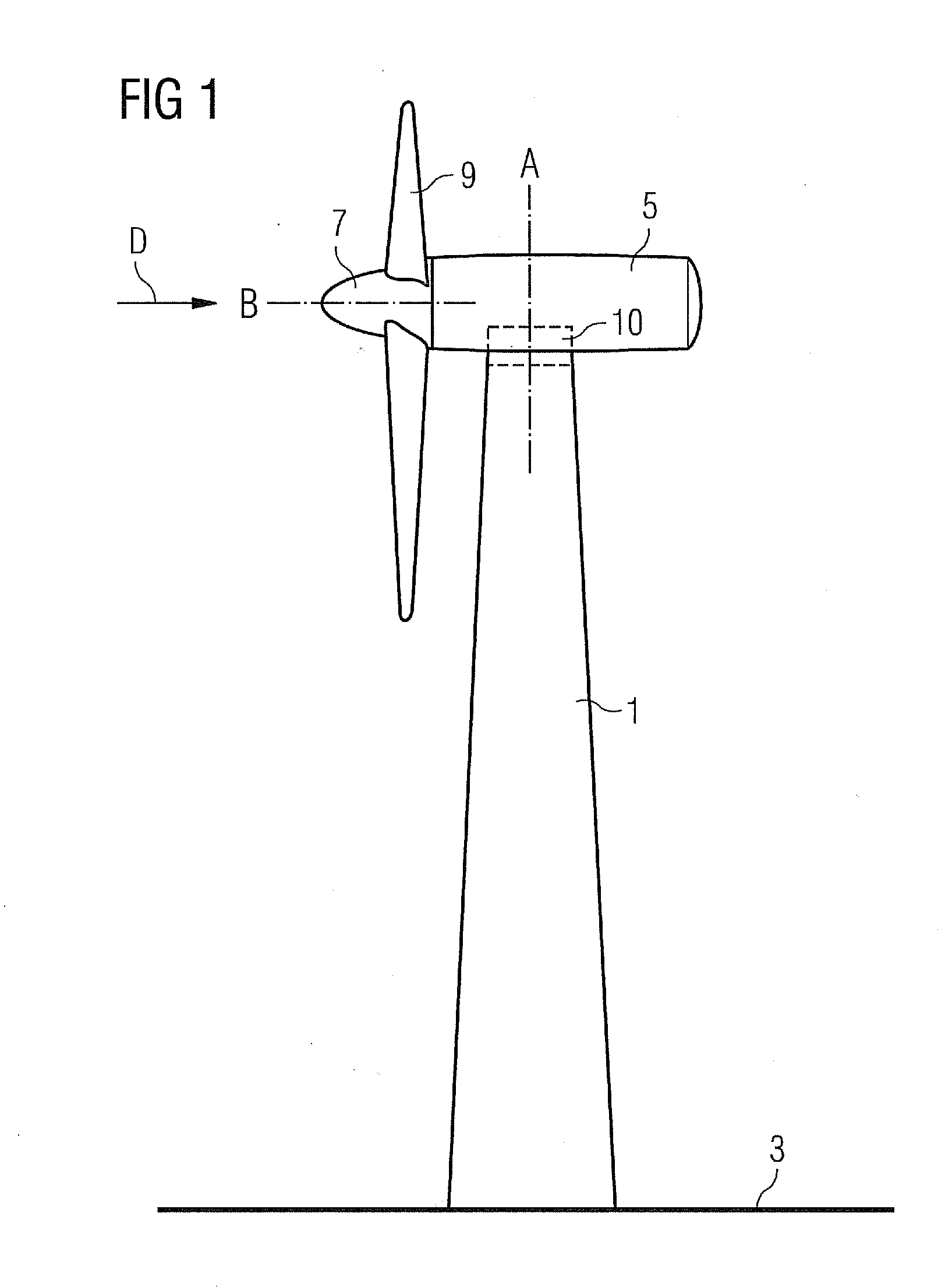
[0023]A yaw drive 10 is arranged between the nacelle 5 and the tower 1 for allowing the nacelle 5 to be rotated about a tower axis A so as to bring the rotor axis B into alignment with the wind direction D and keep the rotor axis B aligned with the wind direction D. Such a yaw drive 10 comprises a ring gear 11 which is typically located at the tower top and one or more pinion gears 13 located at the nacelle 5 which mesh with the ring gear 11 (see FIG. 2)...


PUM


Abstract

A gear assembly is disclosed. The gear assemble includes a ring gear and at least one pinion gear. The ring gear includes a surface which is coated with an abrasion resistant coating and the surface of the at least one pinion gear has a lower hardness than the surface of the ring gear.

Description

CROSS REFERENCE TO RELATED APPLICATIONS[0001]This application claims priority of European Patent Office application No. 10000318.5 EP filed Jan. 14, 2010, which is incorporated by reference herein in its entirety.FIELD OF INVENTION[0002]The present invention relates to a gear assembly comprising a ring gear and at least one pinion gear. In addition, the invention relates to a wind turbine and, in particular, to a wind turbine yaw drive.BACKGROUND OF INVENTION[0003]A wind turbine yaw drive is located between the nacelle and the tower of a wind turbine and serves for rotating the rotor of the wind turbine to alignment with the wind direction. It typically comprises a gear assembly with a ring gear fixed to the tower and a least one motor driven pinion gear fixed to the nacelle. An example for a wind turbine yaw system is described in WO 2008 / 053017 A2. When the wind turbine is not aligned to the wind direction the at least one motor of the yaw drive rotates the nacelle back into wind ...

Claims


Application Information

Patent Timeline
Patent Type & Authority Applications(United States)
IPC IPC(8): F03B7/00F16H55/17
CPCF03D7/0204F03D11/00F05B2280/5007F05C2251/10Y10T74/19642F16H57/041F16H57/0486Y02E10/723Y02E10/722F16H55/17F03D80/00Y02E10/72
Inventor KOLPIN, HELMUTWOHLLEB, MATTHIAS
Owner SIEMENS AG
Why Eureka
Try Eureka