Turbocharger

Active Publication Date: 2011-07-21
FORD GLOBAL TECH LLC +1
View PDF9 Cites 72 Cited by
  • Summary
  • Abstract
  • Description
  • Claims
  • Application Information

AI Technical Summary

Benefits of technology

[0002]Engines may use a turbocharger to improve engine torque/power output density. In one example, a turbocharger may include a compressor and a turbine connected by a drive shaft, where the turbine is coupl

Problems solved by technology

The reversal of air flow may cause the engine to lose power.
During tip-out surge, the engine and the air flow mass through the compressor may slow down, while the turbocharger continues to spin due to inertia and delays through the exhaust system.
The spinning compressor and low air flow rate may cause rapid pressure build-up on the compressor outlet, while the lagging higher exhaust flow rate may cause pressure reduction on the turbine side.
When forward flow through the compressor can no longer be sustainable, a momentary flow reversal occurs, and the compressor is in surge.
High levels of EGR may increase

Method used


Image

  • Turbocharger
  • Turbocharger
  • Turbocharger

Examples


Embodiment Construction

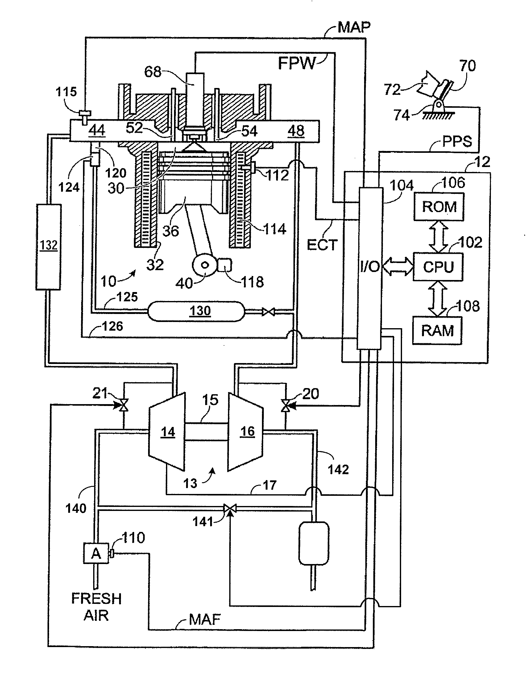
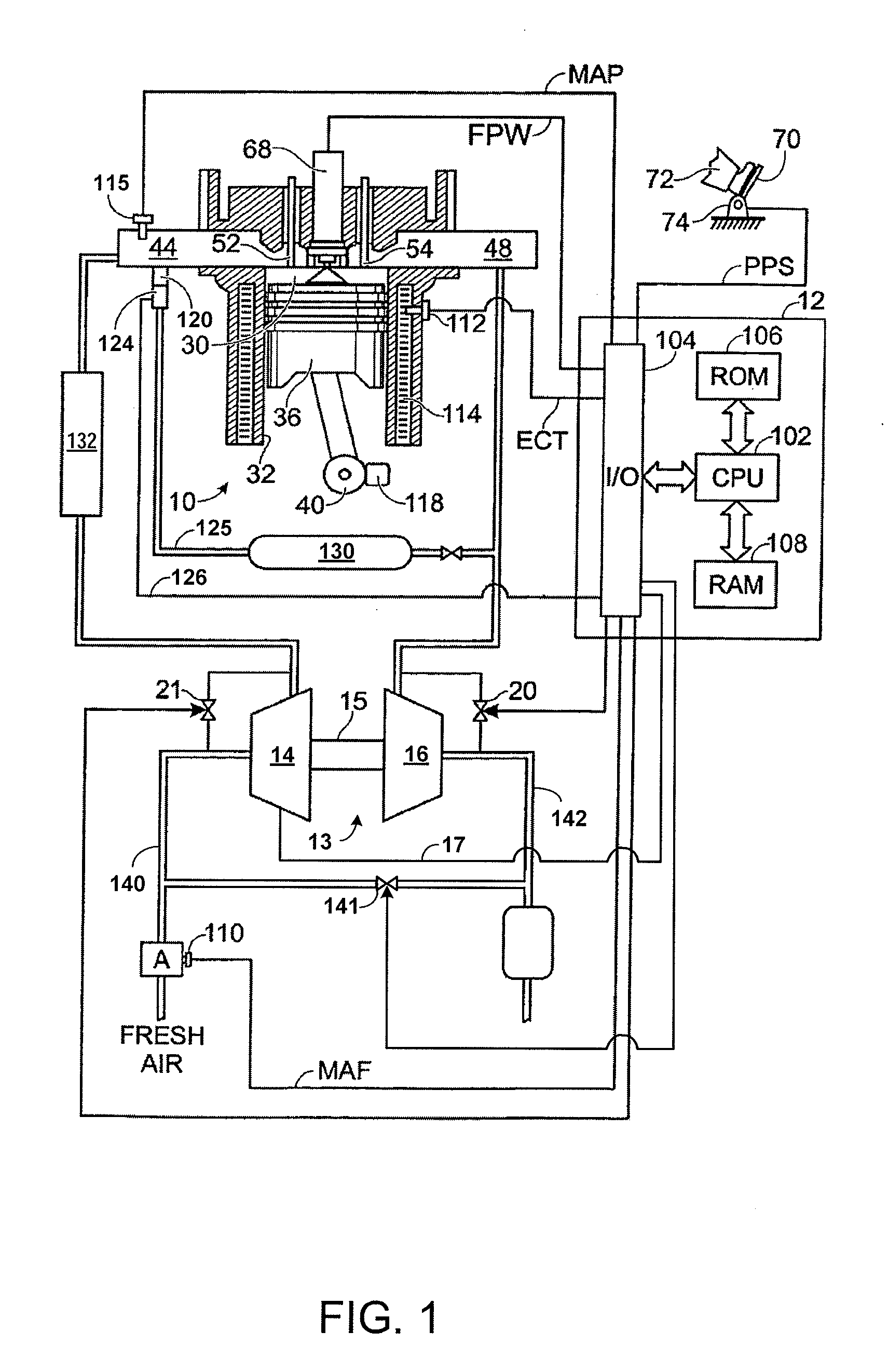
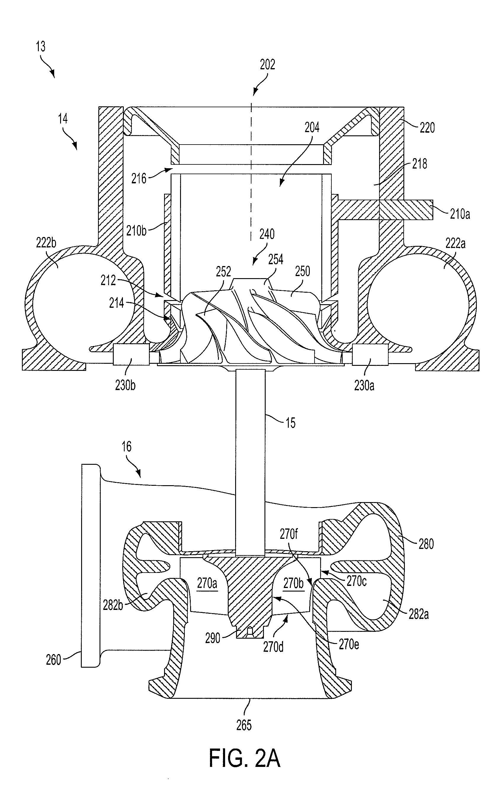
[0023]The following description relates to systems for turbochargers of internal combustion engines with exhaust gas recirculation (EGR). An example embodiment of an engine with a turbocharger and exhaust gas recirculation is illustrated in FIG. 1. The example turbocharger is shown in more detail in FIGS. 2A-2B, such that the components affecting aerodynamic flow through the turbocharger may be examined. In FIG. 2A, a compressor and a turbine in the turbocharger are illustrated. An example embodiment of an impeller blade of a compressor is shown in more detail in FIG. 2A. FIGS. 3A and 3B show a meridional projection of a blade and a cross-section of a blade, respectively, so that various blade characteristics may be defined. FIGS. 4A-4F are tables of prophetic data of impeller blade characteristics that may extend the operating range of the turbocharger. The data from FIGS. 4A-4F are graphed in FIGS. 5A-5B so that generalizations about the data may be observed. FIGS. 6A-6C are table...


PUM


Abstract

In one example, a turbocharger for an internal combustion engine is described. The turbocharger comprises a casing containing an impeller having a full blade coupled to a hub that rotates about an axis of rotation. The casing includes a bleed port and an injection port. The full blade includes a hub edge, a casing edge, and a first distribution of angles, each angle measured between the axis of rotation and a mean line at the hub edge at a meridional distance along the hub edge. The full blade includes a second distribution of angles, each angle measured between the axis of rotation and a mean line at the casing edge at a meridional distance along the casing edge. Further, various systems are described for affecting the aerodynamic properties of the compressor and turbine components in a way that may extend the operating range of the turbocharger.

Description

FIELD[0001]The present application relates to systems for turbochargers of internal combustion engines with exhaust gas recirculation.BACKGROUND AND SUMMARY[0002]Engines may use a turbocharger to improve engine torque / power output density. In one example, a turbocharger may include a compressor and a turbine connected by a drive shaft, where the turbine is coupled to the exhaust manifold side and the compressor is coupled to the intake manifold side. In this way, the exhaust-driven turbine supplies energy to the compressor to increase the flow of air into the engine.[0003]The compressor is intended to work in an operating range between two conditions, surge and choke. Surge occurs during low air mass flow, when the air flow through the compressor stalls and may reverse. The reversal of air flow may cause the engine to lose power. One source of surge, tip-out surge, may occur when the engine suddenly decelerates. During tip-out surge, the engine and the air flow mass through the comp...

Claims


Application Information

Patent Timeline
IPC IPC(8): F02B47/08F02B33/34
CPCF02B47/08F02M25/0707F02M25/0709F04D29/284F04D29/685F05D2220/40Y02T10/121F04D29/4213F04D29/30F02M26/05F02M26/06Y02T10/12
Inventor SUN, HAROLD HUIMINHANNA, DAVEZHANG, JIZHONGHU, LIANGJUNKRIVITZKY, ERIC M.LAROSILIERE, LOUIS M.BAINES, NICHOLAS C.
Owner FORD GLOBAL TECH LLC
Why Eureka
Try Eureka