Nozzle System for Tank Floor

a technology of nozzles and tanks, applied in the direction of mechanical equipment, transportation and packaging, cleaning using liquids, etc., can solve the problems of local sewage treatment plants not being able to handle the added flow, storm water runoff can pose significant problems for sewage water treatment facilities, and contamination of local waterways, etc., to achieve the effect of additional structural and operating advantages

Active Publication Date: 2011-07-28
VAUGHAN
View PDF4 Cites 16 Cited by
  • Summary
  • Abstract
  • Description
  • Claims
  • Application Information

AI Technical Summary

Benefits of technology

[0012]There is disclosed herein an improved tank mixing system and mixing nozzle which avoids the disadvantages of prior devices while affording additional structural and operating advantages. The systems, devices and methods disclosed operate to prevent sediment buildup on a surface, such as a waste-water tank bottom, remove such buildup after it occurs, or both.

Problems solved by technology

Storm water runoff can pose significant issues for sewage water treatment facilities.
Typically, local sewage treatment plants cannot handle the added flow from a rain storm, so they bypass the water treatment and dump thousands of gallons of untreated water into local waterways.
Along with pollutants and toxins, the runoff water can carry with it a great deal of debris and unsettled sediment carried from roadways, parking lots, and the like.
However, where the runoff water is held for long periods of time, the debris and sediment can settle out of the water and deposit on the CSO tank bottom where it may fill the sump and block the pump which sends the water out to the treatment plant.
For all the reasons described above, a loss of overflow volume could lead to contamination of local waterways, such as ponds, lakes, streams and the like.
Another problem with prior systems has to do with nozzle pressure and clogging.
When larger debris, such as shoes, balls, branches, etc., enter the CSO tank, it can quickly clog the 2.5 inch nozzles.
Using six larger 3.5 inch nozzles also precipitously drops system discharge pressure, allowing the centrifugal pump to create too much flow, which leads to the creation of damaging cavitation inside the pump.
Unfortunately, the use of fewer nozzles in large CSO tanks presents an issue in that the resulting system will be unable to properly stir the tank contents while also simultaneously washing away settled debris at the tank center.
This can only be done, of course, when the CSO tank is substantially empty and not in use.

Method used


Image

  • Nozzle System for Tank Floor
  • Nozzle System for Tank Floor
  • Nozzle System for Tank Floor

Examples


Embodiment Construction

[0031]While this invention is susceptible of embodiments in many different forms, there is shown in the drawings and will herein be described in detail a preferred embodiment of the invention with the understanding that the present disclosure is to be considered as an exemplification of the principles of the invention and is not intended to limit the broad aspect of the invention to embodiments illustrated.

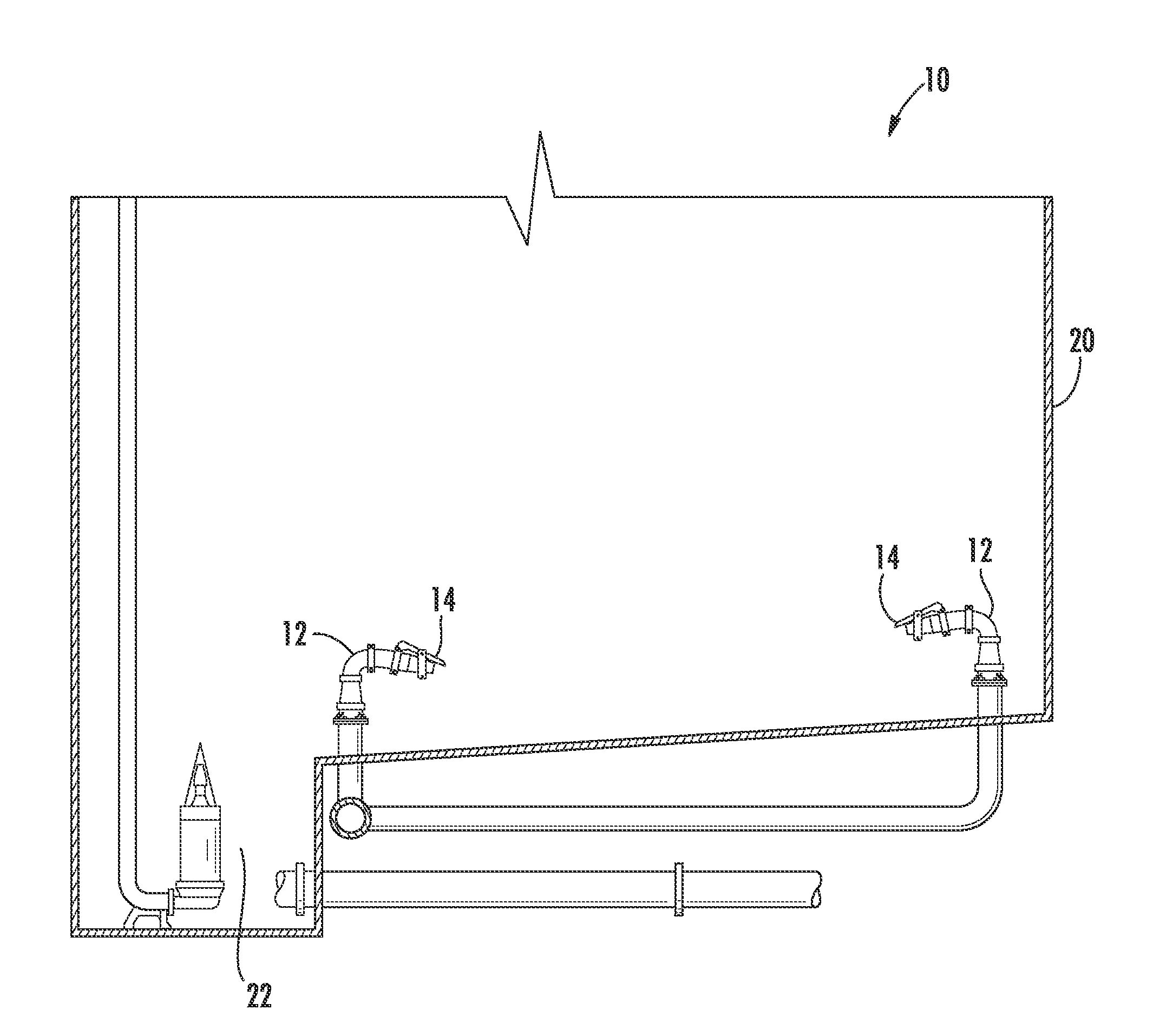
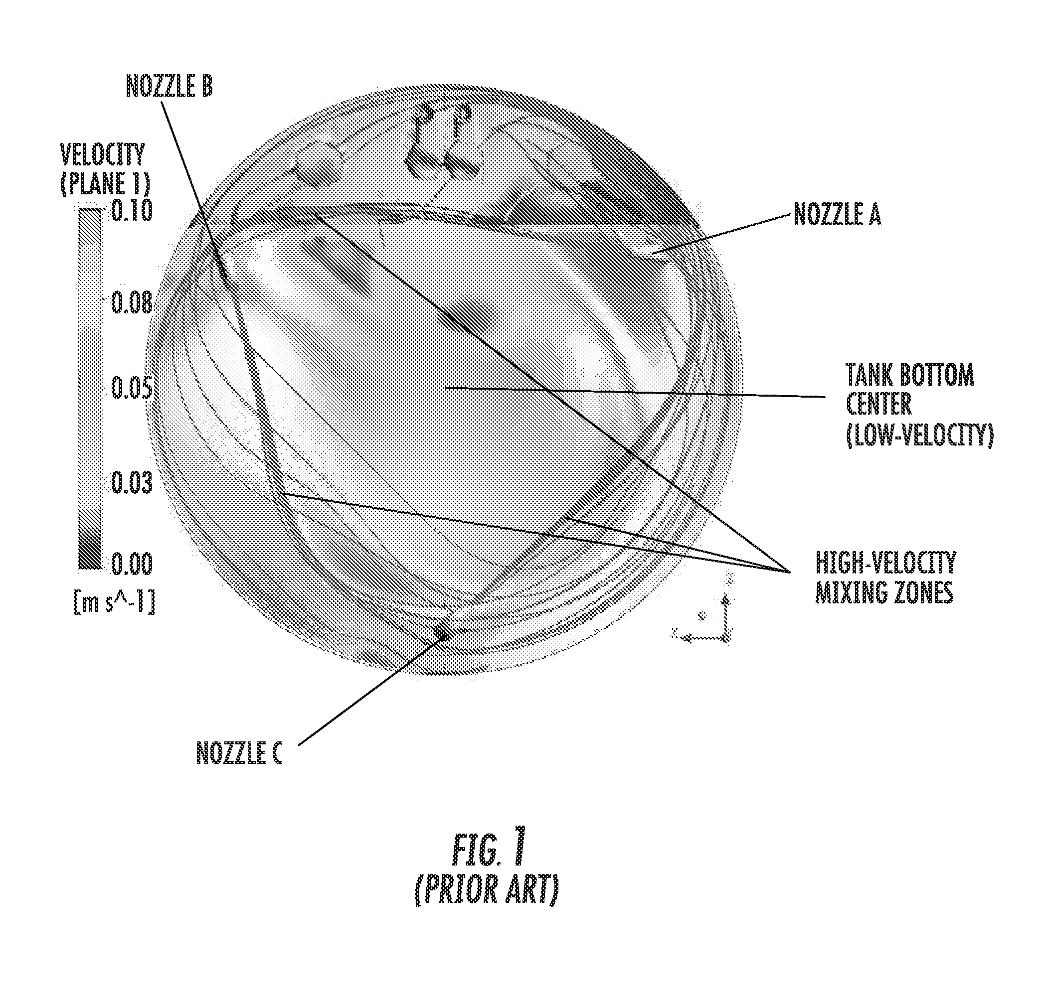
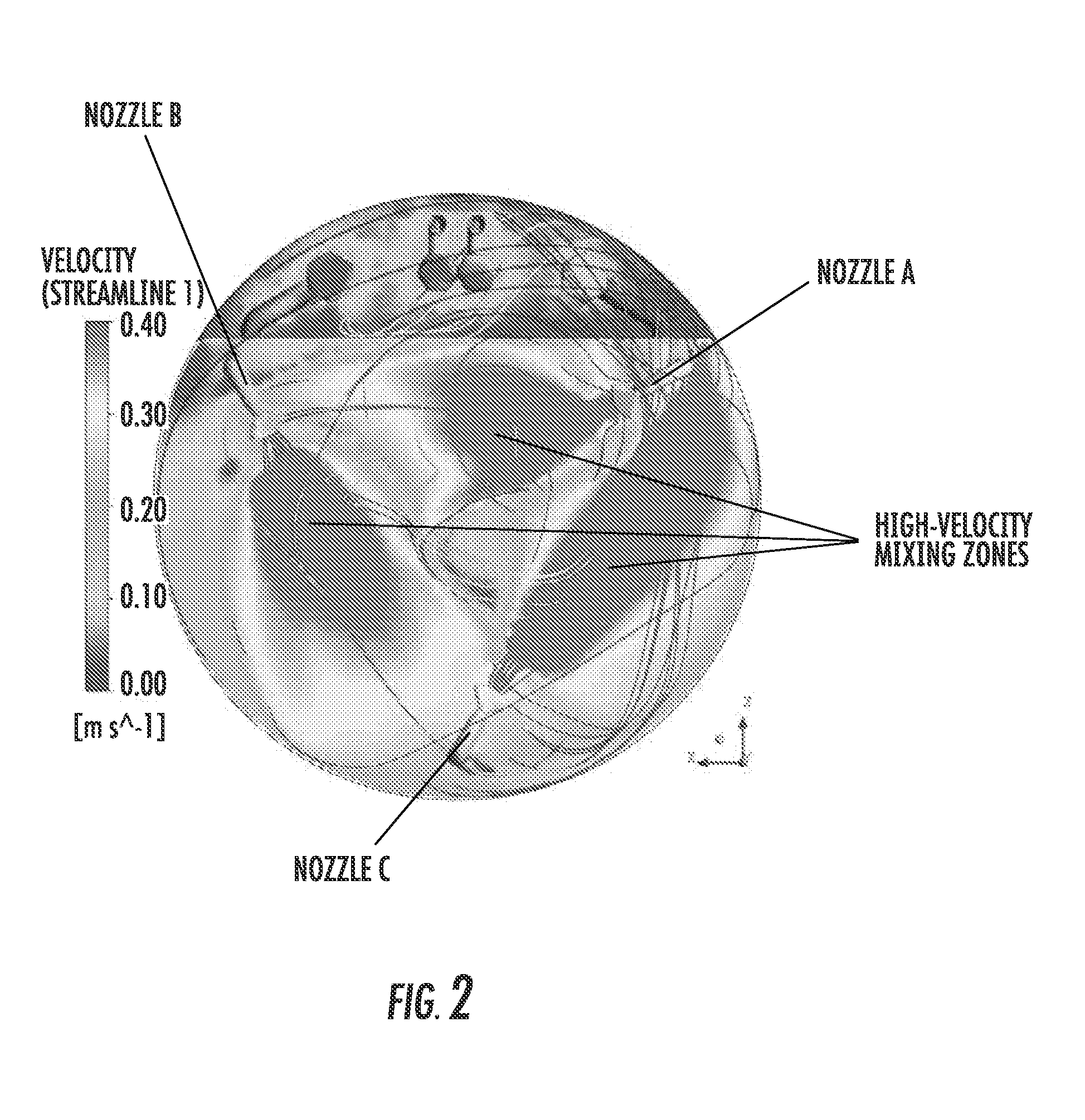
[0032]Referring to FIGS. 2-10, there are illustrated various aspects of a tank mixing and surface scouring system, including methods, generally designated by the numeral 10. While the disclosed embodiments are shown primarily in conjunction with a storage tank, alterations may be made to adapt the system 10 to, for example, mixing tanks of any kind and for most any purpose where solid deposits may cause a problem.

[0033]Generally speaking, a preferred system 10 has a cylindrical tank 20 having a floor sloped toward a sump 22, a plurality of liquid dispensing nozzles 12, a splash pl...


PUM


Abstract

A nozzle system for mixing contents in a tank and scouring surfaces of debris and sediment is disclosed. The system is capable of use either below or above a tank's liquid content surface as well as being adaptable to flow channels and other surfaces which may become impeded with sediment and debris. The nozzle system includes at least one nozzle receiving fluid from a pump, and a splash plate positioned to deflect a discharged stream from the nozzle in a spread and downward direction. The number and positioning of additional nozzles in the system can be determined by mapping the discharge of each splash plate equipped nozzle and arranging for the desired area of coverage.

Description

RELATED APPLICATION[0001]This application is a continuation-in-part and claims the filing priority of co-pending U.S. patent application Ser. No. 12 / 694,396, filed Jan. 27, 2010, titled “System Having Foam Busting Nozzle and Sub-surface Mixing Nozzle” (the '396 application), the contents also of which are hereby incorporated by reference. The '396 application is assigned to the assignee of the present application.TECHNICAL FIELD OF THE INVENTION[0002]The present device relates to a system of nozzles for use on wastewater storage tanks and the like. Particularly, the present device relates to a nozzle system for moving sediment on a tank floor.BACKGROUND OF THE INVENTION[0003]Storm water runoff can pose significant issues for sewage water treatment facilities. Often such facilities have a CSO (Combined Sewage Overflow) system. A CSO system is comprised of a big tank, like a huge swimming pool, that collects the storm water runoff so that the runoff does not just get dumped into the l...

Claims


Application Information

Patent Timeline
Patent Type & Authority Applications(United States)
IPC IPC(8): B08B3/02
CPCB01F5/0206B08B9/0933B01F5/10Y10T137/0424Y10T137/4238B01F25/21B01F25/50
Inventor DORSCH, GLENN R.
Owner VAUGHAN
Why Eureka
Try Eureka