
Clustered magnetic particles as tracers for magnetic particle imaging

Inactive Publication Date: 2011-07-28
KONINKLIJKE PHILIPS ELECTRONICS NV
View PDF6 Cites 7 Cited by
  • Summary
  • Abstract
  • Description
  • Claims
  • Application Information

AI Technical Summary

Benefits of technology

[0012]Arranging, in an individual entity, a controlled number of magnetic particles and / or magnetic particles in a controlled arrangement will lead to new and improved magnetic properties of the whole entity in MPI compared to a single magnetic particle due to the interaction of the magnetic particles in the individual entity. An improved monodispersity in the magnetic properties of the individual entities may provide benefits in numerical quantification and validation of MPI as an imaging technique for molecular medicine.

Problems solved by technology

The interaction between the particles may be constructive or destructive for the MPI signal.
In case such smaller particles are clustered, the interaction between particles is a necessity to yield a good MPI signal, and therefore can be prone to changes in temperature, pH, etc.

Method used


Image

  • Clustered magnetic particles as tracers for magnetic particle imaging
  • Clustered magnetic particles as tracers for magnetic particle imaging
  • Clustered magnetic particles as tracers for magnetic particle imaging

Examples


Embodiment Construction

[0018]A magnetic tracer material comprising clusters of magnetic particles may comprise emulsion based entities. Emulsion based entities may be synthesized using the following process steps:

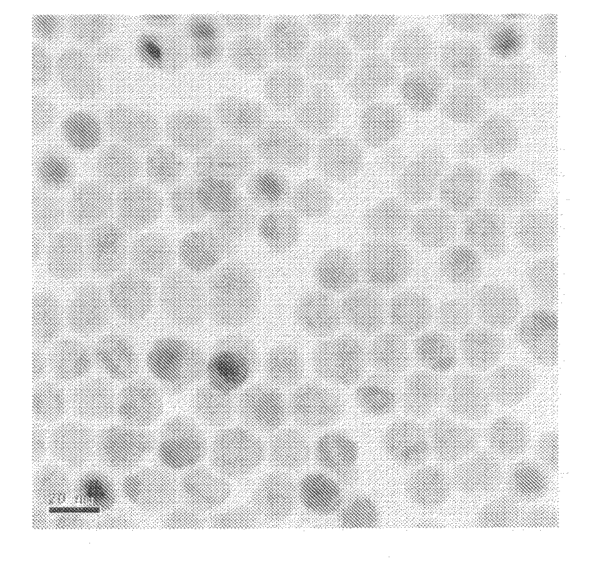
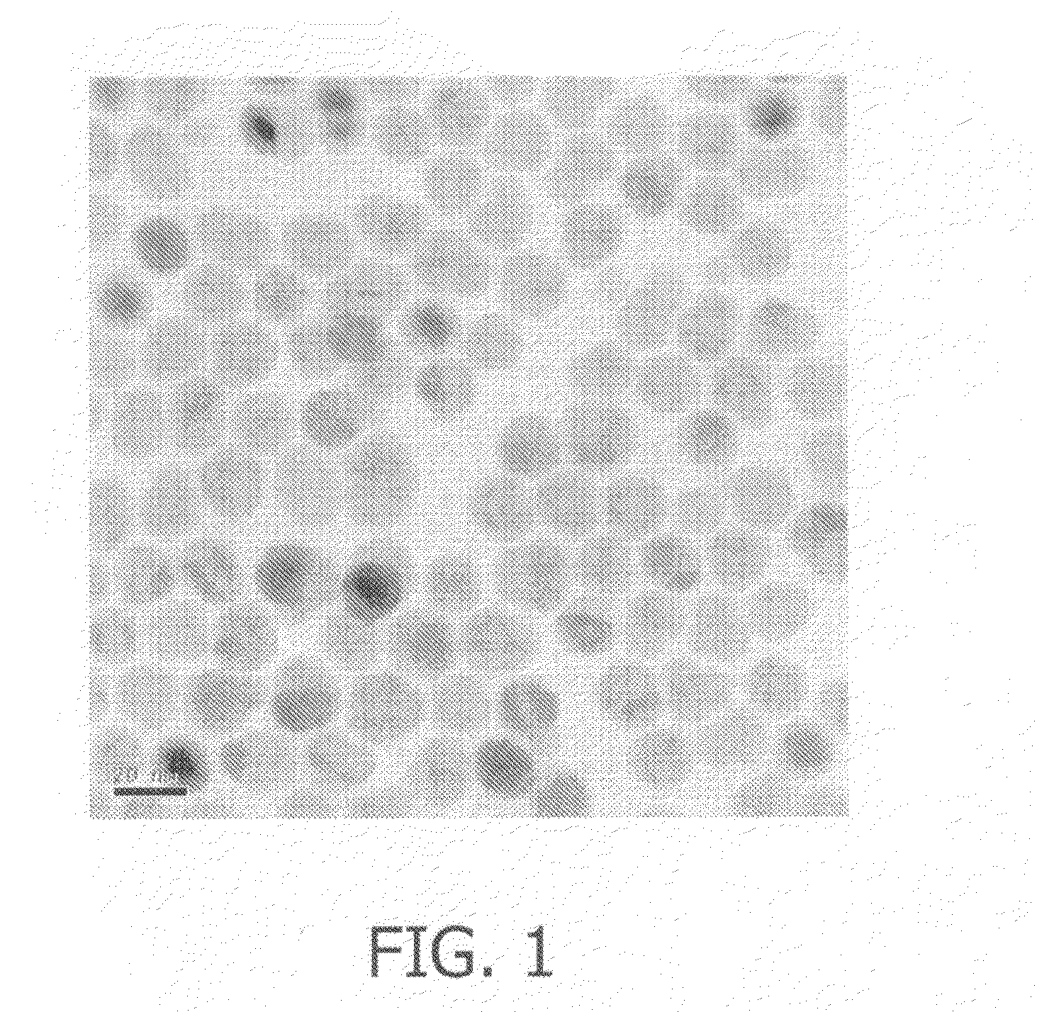
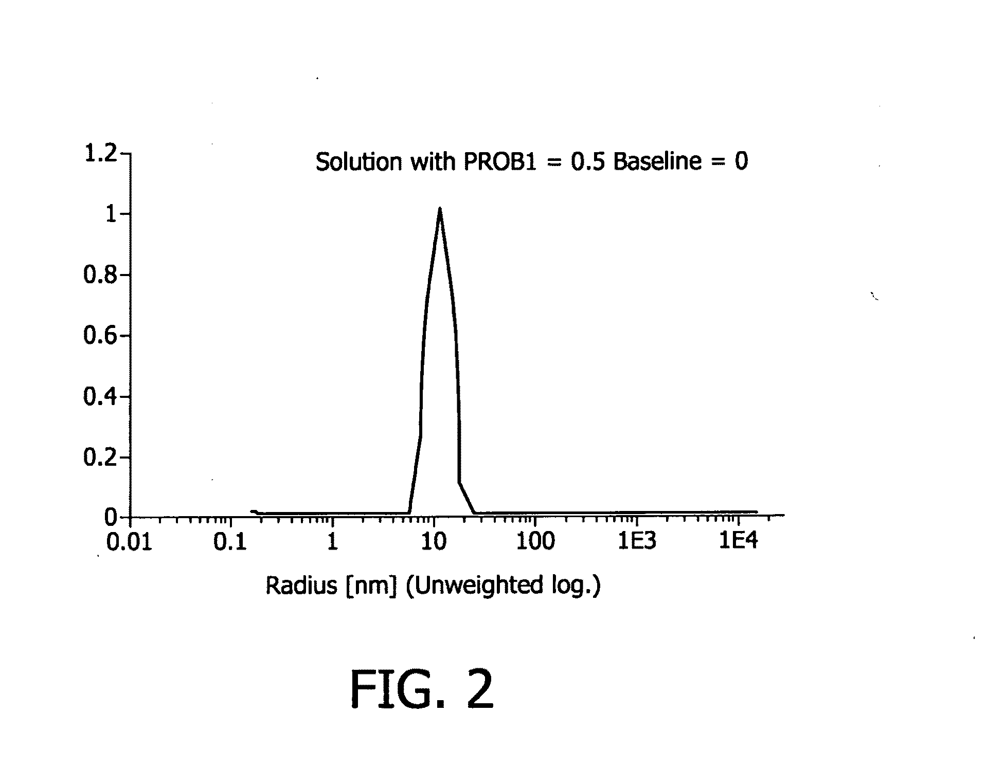
[0019]In a first step, magnetic particles of a well controlled composition, e.g. Fe2O3, Fe3O4, or, generally, FexOy, or doped materials, e.g. Co, Ni, Zn, Mn, . . . :FexOy materials, other magnetic materials such as Fe, Co, Ni, or any other magnetic material of any suitable and well-controlled shape and size are synthesized, preferably in a way that the particles get an hydrophobic surface coating. Examples of the synthesis of such materials are known in the art. In FIG. 1, a TEM picture of hydrophobic coated iron oxide particles is shown. FIG. 2 shows the result of a DLS measurement, whereas in FIG. 3 the result of an X-ray diffraction measurement of iron oxide particles having a size of 20 nm and a hydrophic surface coating of oleic acid is shown. These particles are stable and well dispersed in...


PUM

PropertyMeasurementUnit
Temperatureaaaaaaaaaa
Diameteraaaaaaaaaa
Diameteraaaaaaaaaa

Abstract

The invention provides a magnetic tracer material for use in magnetic particle imaging and a manufacturing method thereof. The magnetic tracer material comprises clusters of a plurality of magnetic particles that are clustered in a controlled way to form individual entities, for example, stabilized oil droplets, solid emulsion particles, liposomes, polymersomes or vesicles, or naturally occurring biological entities such as cells or viruses.

Description

FIELD OF THE INVENTION[0001]The invention relates to magnetic particle compositions for use as magnetic tracers in Magnetic Particle Imaging (MPI) applications.BACKGROUND OF THE INVENTION[0002]Magnetic Particle Imaging (MPI) allows direct 3D imaging of magnetic materials. Spatial images are produced by measuring the magnetic fields generated by magnetic particles introduced in an examination area. As described, for example, in US 2003 / 0085703 A1, a spatially inhomogeneous magnetic field is generated in the examination area, the magnetic field including a first zone in which the magnetization of the particles is in a non-saturated state. In the remaining portion of the examination zone, the magnetic field is strong enough to keep the particles in a state of saturation. Shifting the first zone within the examination area produces a change in the magnetization which can be externally detected and contains information concerning the spatial distribution of the magnetic particles in the ...

Claims


Application Information

Patent Timeline
IPC IPC(8): A61K49/06A61K49/18B29C31/10
CPCA61K49/1812B82Y5/00A61K49/1887
Inventor GRUELL, HOLGERBOEVE, HANS MARC BERTMARKOV, DENIS
Owner KONINKLIJKE PHILIPS ELECTRONICS NV
Learn More