[0007]It is accordingly an object of the invention to provide a thermoelectric device, a thermoelectric apparatus having a multiplicity of thermoelectric devices and a motor vehicle having a thermoelectric apparatus, which overcome the hereinafore-mentioned disadvantages and at least partly solve the highlighted problems of the heretofore-known devices, apparatuses and vehicles of this general type. In particular, the intention is to specify a thermoelectric device which enables an improved efficiency with regard to the conversion of available
thermal energy into electrical energy, copes with changing stresses in the
exhaust gas system of mobile internal
combustion engines and is constructed very compactly.
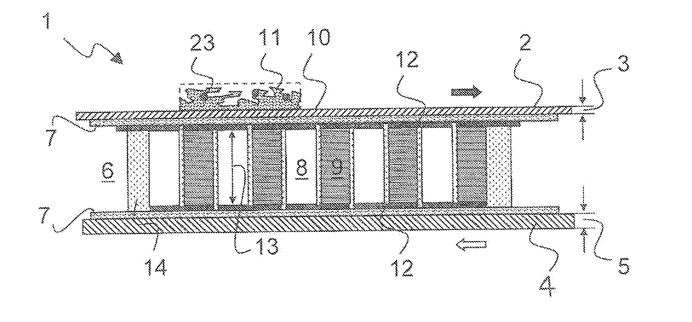
[0011]In order to realize a targeted current flow through the first
semiconductor components and the second
semiconductor components, it is proposed to provide the metallic foils at least partly with an electrical insulation
coating, on which the
semiconductor components are fixed and electrically connected to one another. In particular, at least one aluminum
oxide layer is appropriate as an insulation coating. In this case, the coating thickness should be less than the first material thickness and / or the second material thickness of the metal foils, that is to say e.g. less than 300 μm (micrometers). In the case of the electrical insulation coating, care should be taken to ensure that it does not excessively impede the
heat transfer from an outer side of the metal foil toward the
semiconductor components. This can also be achieved, in particular, by the insulation coating actually only being provided in the region of contact points of the semiconductor components. In all cases, such an electrical insulation coating should be embodied in a sufficiently impermeable fashion in such a way that it is not permeable to the connecting device, in particular
brazing or
soldering material, with the result that
electrically conductive connections toward the metal foil and / or adjacent current paths are reliably avoided through the use of the insulating coating.
[0016]In accordance with a further feature of the invention, with regard to the first metal foil, it can additionally be provided that the first metal foil has a catalyst carrier layer on an outer side facing away from the electrical insulation coating. That can have the effect, in particular, that the first metal foil through its outer side, comes directly into contact with the exhaust gases of an
internal combustion engine. In particular, a
zeolite layer and / or so-called washcoat are / is appropriate as the catalyst carrier layer. Moreover, it is possible for the catalyst carrier layer actually to include a catalyst, in particular noble metals, disposed in a manner distributed in and / or on the catalyst carrier layer. In the case of the layer height of the catalyst carrier layer, consideration should be given to ensuring that the latter does not significantly impede the
heat transfer from the exhaust gas toward the semiconductor components in the interspace of the thermoelectric device. If appropriate, this can be compensated for by initiating exothermic reactions with the catalyst on the outer side, in such a way that additional heat can be liberated in this case on site.
[0018]In accordance with an additional feature of the invention, it is advantageous for the multiplicity of first semiconductor components and second semiconductor components to have a component height of 1 mm to 5 mm (millimeters). This firstly leads to a very compact configuration of the thermoelectric device and secondly ensures a sufficient
temperature difference between the first metal foil and the second metal foil across the interspace. A component height in the range of 1 to 2 mm is especially preferred. All of the semiconductor components will regularly have the same component height.
[0021]In accordance with yet an added feature of the invention, it is also considered to be advantageous to have at least one layered construction. If appropriate, it is also possible for a portion of the first semiconductor components and second semiconductor components or it also possible for all of the semiconductor components, to be constructed in a layered manner. Since a particularly filigree thermoelectric device can be produced in this case, the layered application e.g. through the use of printing, of the material onto the metal foils can be realized particularly simply and process-reliably.

