Monitoring and camera system and method

a camera system and camera technology, applied in the field of camera based monitoring systems, can solve the problems of difficult to capture the wide dynamic range of light during such processes using conventional cameras, the inability to monitor feed stock, and the inability to use a darkened window to always enable viewing of feed stock

Inactive Publication Date: 2011-08-04
EDELSON STEVEN DONALD
View PDF43 Cites 60 Cited by
  • Summary
  • Abstract
  • Description
  • Claims
  • Application Information

AI Technical Summary

Benefits of technology

[0024]FIG. 6 is a graph showing the effects of gain and offset correction in varying ambient light.

Problems solved by technology

Using a darkened window does not always enable viewing of the feed stock, the liquid material pool, the tool tip, and the like.
It is also very difficult to capture the wide dynamic range of light during such processes using conventional cameras although a fairly wide dynamic range from the brightest to darkest details at the site can be captured by a logarithmic sensor.
The arc, in addition to being extremely bright, also changes in intensity so exposure of the site image can be uneven between rows in an image and between individual video frame images.
The known prior art is primarily limited to addressing lighting conditions which change in a predictable fashion, for example, when fluorescent lighting is used.
The result can be a relatively long exposure which can be problematic.
Also, this technique is based on the assumption that the light variation is periodic which is not necessarily true in some environments including arc welding.

Method used


Image

  • Monitoring and camera system and method
  • Monitoring and camera system and method
  • Monitoring and camera system and method

Examples


Embodiment Construction

[0025]Aside from the preferred embodiment or embodiments disclosed below, this invention is capable of other embodiments and of being practiced or being carried out in various ways. Thus, it is to be understood that the invention is not limited in its application to the details of construction and the arrangements of components set forth in the following description or illustrated in the drawings. If only one embodiment is described herein, the claims hereof are not to be limited to that embodiment. Moreover, the claims hereof are not to be read restrictively unless there is clear and convincing evidence manifesting a certain exclusion, restriction, or disclaimer.

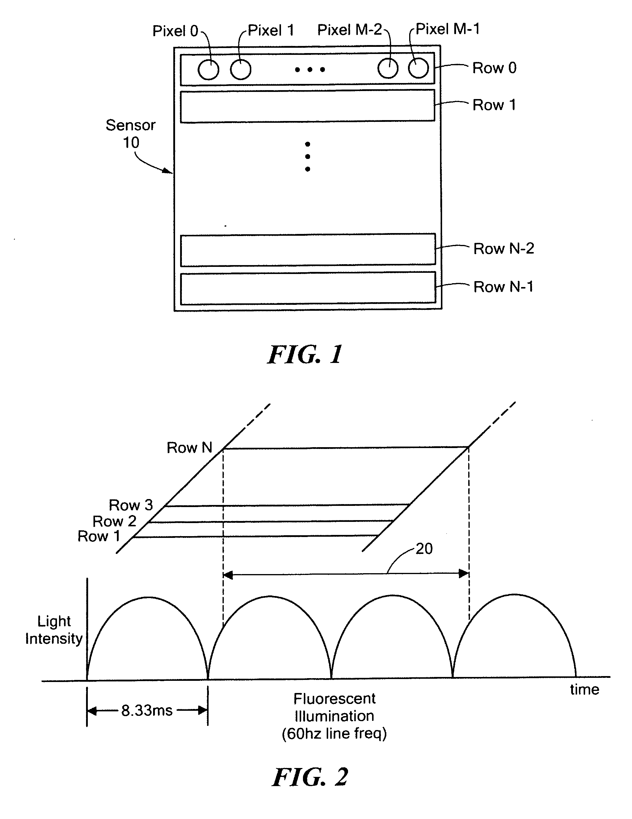
[0026]FIG. 1 depicts an example of an image sensor 10 including rows and columns of pixels. There are N rows each containing M pixel locations. The pixel data is usually read out sequentially left to right along a row, row by row, top to bottom, or the like. Internally, the pixel light sensing elements collect charge or vol...


PUM


Abstract

A monitoring system includes an image sensor configured to produce pixel data. An ambient light sensor such as a photocell produces ambient light level data. A processing subsystem is programmed to adjust the pixel data based on the ambient light level data. For example, the gain of an analog to digital converter can be increased or decreased based on the ambient light level data to adjust analog pixel data output by the imager as it is converted to digital data. If the ambient light level is high, for example, the gain can be decreased.

Description

RELATED APPLICATIONS[0001]This application hereby claims the benefit of and priority to U.S. Provisional Application Ser. No. 61 / 261,304, filed on Nov. 13, 2009 under 35 U.S.C. §§119, 120, 363, 365, and 37 C.F.R. §1.55 and §1.78.FIELD OF THE INVENTION[0002]The subject invention relates to camera based monitoring systems.BACKGROUND OF THE INVENTION[0003]It is often desirable to monitor processes such as welding or metal cutting where a high energy electric arc, plasma, torch flame, laser, electron beam or other high energy source is used. The welding can be very bright and becomes the dominant illumination source for the area surrounding it illuminating the area to many times the brightness as would come from other lighting at the site. Using a darkened window does not always enable viewing of the feed stock, the liquid material pool, the tool tip, and the like.[0004]It is also very difficult to capture the wide dynamic range of light during such processes using conventional cameras ...

Claims


Application Information

Patent Timeline
Patent Type & Authority Applications(United States)
IPC IPC(8): H04N5/235H04N7/18H04N5/335
CPCH04N5/353H04N5/2351H04N23/71H04N25/53
Inventor EDELSON, STEVEN DONALD
Owner EDELSON STEVEN DONALD
Why Eureka
Try Eureka