Heat Transfer Label Having a UV Layer

Active Publication Date: 2011-08-04
MULTI COLOR CORP
View PDF42 Cites 20 Cited by
  • Summary
  • Abstract
  • Description
  • Claims
  • Application Information

AI Technical Summary

Benefits of technology

[0012]Certain exemplary aspects of the invention are set forth below. It should be understood that these aspects are presented merely to provide the reader with a brief summary of certain forms the invention might take and that these aspects are not intended to li

Problems solved by technology

However, there are drawbacks to using rotogravure printing.
Problems with this method of preparing such labels include the fact that the cost of tooling to produce the labels (i.e., the cost of preparing engraved cylinders) is very expensive.
However, the solvent-based components that are used when making heat transfer labels pose a number of drawbacks.
In particular, such solvent-based components raise health, safety, and environmental concerns.
Mixtures of solvent vapors and air can explode.
Solvent vapors are heavier than air, and so they can and will sink and can travel large distances in an undiluted or nearly undiluted state.
Solvent vapors can also be found in supposedly empty drums and cans, posing a flash fire hazard.
Further, many solvents can lead to a sudden loss of consciousness if inhaled in large amounts.
And, some solvents pose health issues—such as chloroform and benzene, which are carcinogenic.
Many others can damage internal organs like the liver, the kidneys, or the brain.
More solvent-related health issues arise from spills or leaks of solvents that reach the underlying soil.
Since solvents readily migrate substantial distances, the creation of widespread soil contamination is not uncommon.
These problems also result in many difficulties, and in high costs, of using solvent-based materials and disposing of solvents or solvent waste during and following production runs.
One reason that flexographic printing has not been pursued aggressively until recently is that the chemistry of the solvent inks are incompatible with the photopolymer

Method used


Image

  • Heat Transfer Label Having a UV Layer
  • Heat Transfer Label Having a UV Layer
  • Heat Transfer Label Having a UV Layer

Examples


Example

Example 1

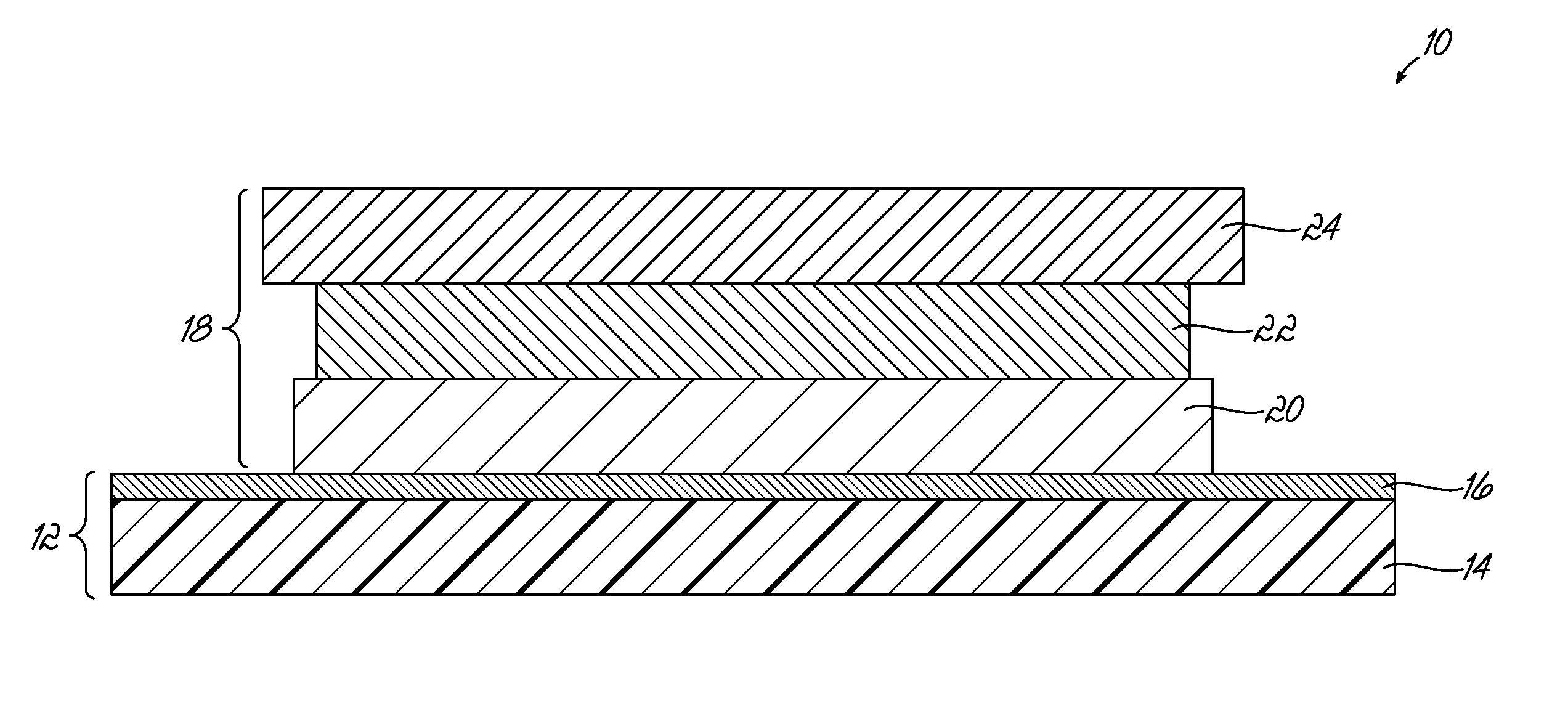
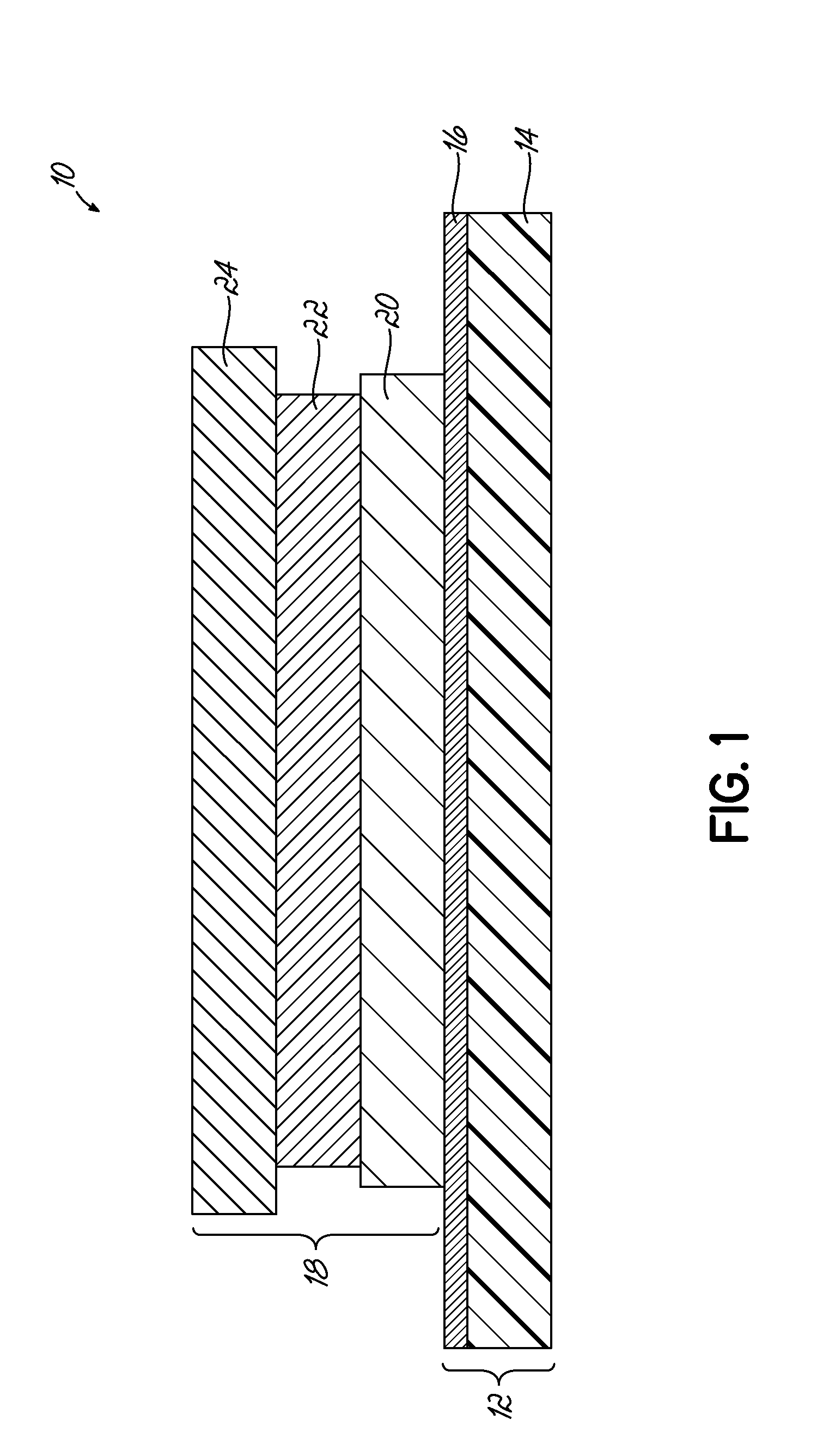
[0083]A heat transfer label was formed by printing the components of the transfer portion as described in the embodiment of FIG. 3. A solvent protective lacquer, Gotham PL2 Varnish 46-1333, was applied to a wax release paper using conventional flexographic printing techniques, well known to those of ordinary skill in the art. The solvent lacquer was dried in a conventional enclosed hot air dryer, well known to those of ordinary skill in the art.

[0084]A design was then printed over the protective lacquer layer using Gotham Ink Company FP-500 NUV series UV-curable inks using conventional flexographic printing techniques. 600 W GEW UV lamps were used after the application of each ink layer to cure the ink. Complete cure of the ink was observed with no tracking or smudging. A solvent adhesive layer, Gotham Ad-Bond Adhesive 46-1335, was then overprinted on the design. The solvent adhesive layer 24 was dried in a conventional enclosed hot air dryer. The resulting web was wound in...

Example

Example 2

[0088]A heat transfer label was formed by printing the components of the transfer portion as described in the embodiment of FIG. 4. A solvent protective lacquer, Gotham PL2 Varnish 46-1333, was applied to a wax release paper using conventional flexographic printing techniques. The solvent lacquer was dried in a conventional enclosed hot air dryer.

[0089]A design was then printed over the protective lacquer layer using Gotham Ink Company FP-500 NUV series UV-curable inks using conventional flexographic printing techniques. 600 W GEW UV lamps were used after the application of each ink layer to cure the ink. Complete cure of the ink was observed with no tracking or smudging.

[0090]A UV tie-coat layer, Gotham FP-500 NUV75, was then overprinted on the design. 600 W GEW UV lamps were used to cure the tie-coat layer. Complete cure of the layer was observed with no tracking or smudging.

[0091]A solvent adhesive layer, Gotham Ad-Bond Adhesive 46-1335, was then overprinted on the desig...

Example

Example 3

[0097]A heat transfer label was formed by printing the components of the transfer portion as described in the embodiment of FIG. 5. A solvent protective lacquer, Gotham PL2 Varnish 46-1333, was applied to a wax release paper using conventional flexographic printing techniques. The solvent lacquer was dried in a conventional enclosed hot air dryer.

[0098]A design was then printed over the protective lacquer layer using Gotham Ink Company FP-500 NUV series UV-curable inks using conventional flexographic printing techniques. 600 W GEW UV lamps were used after the application of each ink layer to cure the ink. Complete cure of the ink was observed with no tracking or smudging.

[0099]A UV tie-coat layer, Gotham FP-500 NUV75, was then overprinted on the design. 600 W GEW UV lamps were used to cure the tie-coat layer. Complete cure of the layer was observed with no tracking or smudging.

[0100]A UV-curable adhesive, Gotham FP-500 NUV85, was then overprinted on the design. 600 W GEW UV...


PUM

PropertyMeasurementUnit
Fractionaaaaaaaaaa
Fractionaaaaaaaaaa
Fractionaaaaaaaaaa

Abstract

A heat transfer label and method for preparing same, the heat transfer label including (a) a support portion and (b) a transfer portion over the support portion, for transfer of the transfer portion from the support portion to an article upon application of heat to the support portion while the transfer portion is placed into contact with the article. The transfer portion includes at least a protective lacquer layer, an ink layer, and an adhesive layer, wherein at least one of the protective lacquer layer, the ink layer, and the adhesive layer is UV-curable. Further, the heat transfer label may additionally include a tie-coat layer, which may be a UV-curable tie-coat layer. Further, each of the plurality of layers of the transfer portion of the heat transfer label may be UV-curable.

Description

FIELD OF THE INVENTION[0001]The present invention relates generally to labels for various articles, and relates more specifically to heat transfer labels for articles, such as containers.BACKGROUND OF THE INVENTION[0002]This section is intended to introduce the reader to various aspects of art that may be related to various aspects of the present invention, which are described and / or claimed below. This discussion is believed to be helpful in providing the reader with background information to facilitate a better understanding of various aspects of the present invention. Accordingly, it should be understood that these statements are to be read in this light, and not as admissions of prior art.[0003]Heat transfer labels are multilayered laminates, with each layer having its own function. For example, heat transfer labels generally include an adhesive layer, an ink design layer, and a release layer. The release layer may be a wax release layer, and is often directly adjacent a carrier...

Claims


Application Information

Patent Timeline
IPC IPC(8): G09F3/10B32B7/12B32B7/06C09J7/02C09J7/20
CPCB32B7/06B32B7/12Y10T428/2817G09F3/10Y10T428/2826C09J7/02C09J7/20B44C1/1712B41M3/12B32B2307/75B32B27/08
Inventor MIRACLE, RONALD L.BUSHMAN, ALEXANDER CRAIGLAPRADE, JEAN PAUL
Owner MULTI COLOR CORP
Why Eureka
Try Eureka