Moving Object, Wireless Power Feeding System, and Wireless Power Feeding Method

a technology of wireless power feeding and moving objects, which is applied in the direction of safety/protection circuits, wheelchairs/patients, rail devices, etc., can solve the problems of low conversion efficiency, inability to charge the secondary battery in time, and the driver of the moving object's instance, so as to reduce the strength of a radio wave, reduce power loss, and position relationship

Active Publication Date: 2011-08-11
SEMICON ENERGY LAB CO LTD
View PDF20 Cites 88 Cited by
  • Summary
  • Abstract
  • Description
  • Claims
  • Application Information

AI Technical Summary

Benefits of technology

[0010]In addition, in many cases, the antenna of the power feeding device outputs a substantially constant high power radio wave. Thus, if the conversion efficiency for charging is low due to misalignment between the antennas, power may be dissipated and a high power radio wave which has not been converted into electric energy may be radiated to the surroundings. Although it is known that irradiation of the radiated radio wave on a living body such as a human body causes no problem since most of the radiated radio wave is absorbed into the body and is changed into heat, an effect of a radio wave on a living body has not yet been completely explained. Therefore, it is desirable to reduce the strength of the radio wave radiated to the surroundings.
[0011]In consideration of the above problems, an object of the present invention is to provide a structure of a moving body which enables reduction of power loss caused when power is supplied from a power feeding device to a moving object by wireless communication. Another object of the present invention is to provide a structure of a moving body which enables reduction of the strength of a radio wave radiated to the surroundings.
[0012]Another object of the present invention is to provide a wireless power feeding system and a wireless power feeding method which enable reduction of power loss when power is supplied from a power feeding device to a moving object by wireless communication. Another object of the present invention is to provide a wireless power feeding system and a wireless power feeding method which enable reduction in strength of a radio wave, which is radiated from a power feeding device to the surroundings during a charging operation.
[0021]According to one embodiment of the present invention, the positional relationship between the antenna of the power feeding device and the antenna of the moving object can be easily optimized, which may result in reduction of power loss which may be caused when the battery is charged. In addition, it is possible to reduce the strength of a radio wave radiated to the surroundings from the power feeding device without being used for charging.

Problems solved by technology

That is, misaligmnent between the positions of the power feeding device and the antenna of the moving object leads to a low conversion efficiency, which results in inefficient charging of the secondary battery.
However, it is difficult in most instances for a driver of the moving object to recognize the positional relationship between the antennas of the moving object and the power feeding device while driving the moving object, although it depends on where the antennas are installed.
Thus, if the conversion efficiency for charging is low due to misalignment between the antennas, power may be dissipated and a high power radio wave which has not been converted into electric energy may be radiated to the surroundings.
Although it is known that irradiation of the radiated radio wave on a living body such as a human body causes no problem since most of the radiated radio wave is absorbed into the body and is changed into heat, an effect of a radio wave on a living body has not yet been completely explained.

Method used


Image

  • Moving Object, Wireless Power Feeding System, and Wireless Power Feeding Method
  • Moving Object, Wireless Power Feeding System, and Wireless Power Feeding Method
  • Moving Object, Wireless Power Feeding System, and Wireless Power Feeding Method

Examples


embodiment 1

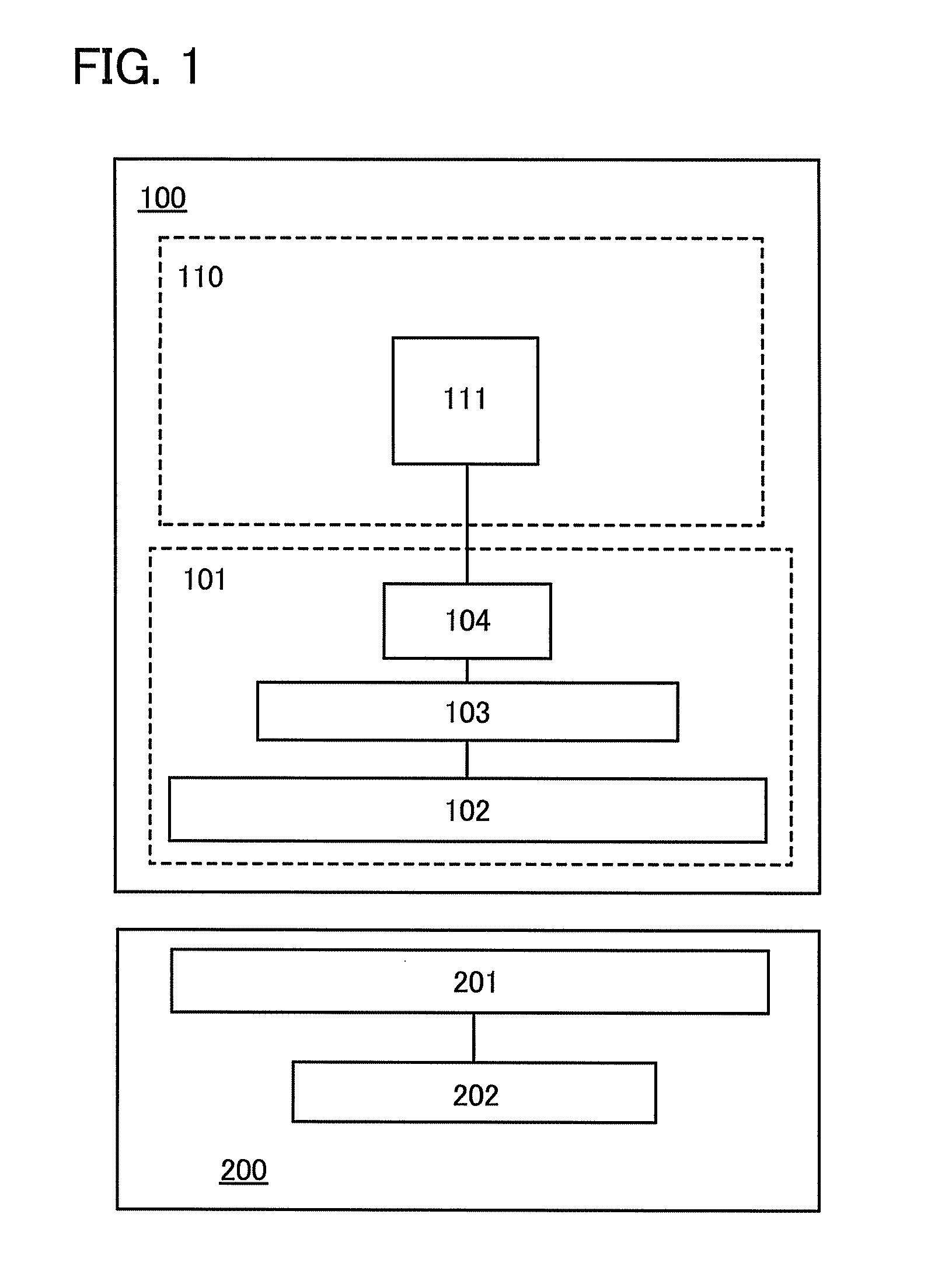
[0038]A configuration of a moving object and a wireless power feeding system using the moving object and a power feeding device according to one embodiment of the present invention are shown in a block diagram of FIG. 1 by way of an example. Although the block diagram shows separate elements within the moving object or the power feeding device according to their functions, as independent blocks, it may be practically difficult to completely separate the elements according to their functions and, in some cases, one element may involve a plurality of functions.

[0039]As shown in FIG. 1, a moving object 100 includes a power receiving device portion 101 and a power load portion 110. The power receiving device portion 101 includes at least a moving object antenna circuit 102, a signal processing circuit 103, and a secondary battery 104. In addition, the power load portion 110 includes at least an electric motor 111.

[0040]In addition, the secondary battery 104 is a charge storage means. Ex...

embodiment 2

[0057]In this embodiment, more detailed configurations of the moving object and the wireless power feeding system using the moving object and the power feeding device according to one embodiment of the present invention will be described.

[0058]The configurations of the moving object and the wireless power feeding system using the moving object and the power feeding device according to one embodiment of the present invention are shown in a block diagram of FIG. 2 by way of an example. As shown in FIG. 2, the moving object 100 includes the power receiving device portion 101 and the power load portion 110 as in FIG. 1.

[0059]The power receiving device portion 101 includes at least the moving object antenna circuit 102, the signal processing circuit 103, the secondary battery 104, a rectifier circuit 105, a modulation circuit 106 and a power supply circuit 107.

[0060]The power load portion 110 includes at least the electric motor 111 and a driving portion 112 whose operation is controlled...

embodiment 3

[0104]In this embodiment, the positional relationship between a moving object antenna circuit of a moving object and a power feeding device antenna circuit of a power feeding device will be described.

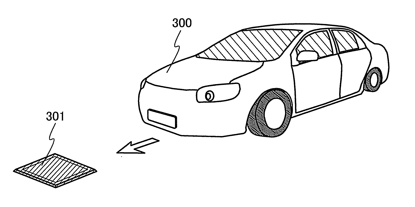
[0105]FIG. 8A shows a state where a four-wheeled automobile 300 as one of moving objects approaches a power feeding device antenna circuit 301 of the power feeding device. The automobile 300 approaches the power feeding device antenna circuit 301 in a direction indicated by an arrow.

[0106]The automobile 300 includes a moving object antenna circuit 302 provided on its bottom portion. In order to clearly show the position of the moving object antenna circuit 302 in the automobile 300, FIG. 8B shows the outline of the automobile 300 and the moving object antenna circuit 302 provided on the bottom portion of the automobile 300.

[0107]As the automobile 300 moves in the direction of the arrow, the moving object antenna circuit 302 provided on the bottom portion of the automobile 300 finally be...


PUM


Abstract

An object is to provide a moving object structure capable of reducing power loss caused when power is supplied from a power feeding device to a moving object by wireless communication. Another object is to provide a moving object structure capable of reducing the strength of a radio wave radiated to the surroundings. Before power is supplied to a moving object, a radio wave for alignment of antennas is output from a power feeding device. That is, radio waves are output from a power feeding device in two stages. In a first stage, a radio wave is output to align positions of antennas of the power feeding device and the moving object. In a second stage, a radio wave is output to supply power from the power feeding device to the moving object.

Description

BACKGROUND OF THE INVENTION[0001]1. Field of the Invention[0002]The present invention relates to a moving object which is driven by an electric motor and includes a secondary battery chargeable by wireless communication. The present invention also relates to a wireless power feeding system including a moving object and a power feeding device which supplies power to the moving object through wireless communication. The present invention further relates to a wireless communication method for use in the wireless power feeding system.[0003]2. Description of the Related Art[0004]In recent years, energy saving, creation and storage technologies are attracting more attention because environmental problems such as global warming are becoming more severe. In the case of a moving object with a secondary battery, i.e., a moving object which is driven by an electric motor using power provided from a secondary battery, including but not limited to a two-wheeled vehicle or a four-wheeled vehicle ...

Claims


Application Information

Patent Timeline
Patent Type & Authority Applications(United States)
IPC IPC(8): H02J7/02H02J7/00B60L5/00B60M7/00
CPCB60L5/005Y02T90/121B60L11/1829H01F38/14H02J7/025Y02T10/7005Y02T10/92Y02T90/12Y02T90/122Y02T90/125Y02T90/14B60L11/1833B60L2200/32B60L2200/34Y02B60/50Y02T10/7016Y02T10/7011B60L2200/26B60L11/182Y02T10/7072B60L53/38B60L53/36H02J50/10H02J50/90B60L53/126B60L53/122B60L53/124H02J2310/48H02J7/00302Y02T90/16Y02T10/70H02J50/20B60L53/12B60L2200/10B60L2200/12B60Y2200/91H02J50/12
Inventor YAMAZAKI, SHUNPEIKOYAMA, JUNSHIONOIRI, YUTAKA
Owner SEMICON ENERGY LAB CO LTD
Why Eureka
Try Eureka