Method and grinding machine for the complete grinding of short and/or rod-shaped workpieces

a technology of workpieces and grinding machines, which is applied in the direction of grinding machines, grinding machine components, grinding/polishing apparatus, etc., can solve the problems of difficult to supply the grinding zone with cooling lubricant, inability to achieve the same material removal rate, and limited method to geometric cross-sections with straight edges, etc., to achieve the effect of improving the accuracy of products, reducing the cost of production and improving the speed of machining

Active Publication Date: 2011-08-11
ERWIN JUNKER MASCHNINENFAB
View PDF12 Cites 13 Cited by
  • Summary
  • Abstract
  • Description
  • Claims
  • Application Information

AI Technical Summary

Benefits of technology

[0033]In another embodiment of the invention, the second grinding wheel in the inventive grinding machines which conforms to the longitudinal contour of the finished rod-shaped workpiece can also include its end-face bevels. Machining the lateral workpiece surfaces with numerically controlled circumferential grinding using the C-X interpolation principle makes it possible for rounding radii or bevels to be ground on the edges together with the lateral surfaces without lengthening the cycle. This is also true for the end-face bevels if the contour of the grinding wheel is appropriately profiled. The end-face bevels are ground in the same clamping in one contour pass concurrent with the lateral surfaces and with the bevels or rounding radii running longitudinally. There is no re-clamping. The process is significantly simpler and more certain overall in terms of the required geometry data (dimensional tolerances, shape and position tolerances). Not only is machining time saved, but in particular the risk of inaccuracies associated with re-clamping is also avoided. In addition, the contour of the grinding wheels during dressing must be adjusted with an accuracy in the μm range. Thus there are end-face bevels that always have exactly the same width among one another and for their entire length. In this respect, as well, the invention improves both the speed of the machining and the accuracy of the product. Moreover, it is also possible to use profiled grinding wheels, for instance galvanically coated grinding wheels, that do not have to be dressed.
[0034]In an advantageous and preferred embodiment of the drive for the timing disk, the timing disk can be driven both in the forward direction and also in the opposite, backward direction. This makes it possible to grind substantially concurrently with both grinding wheels, each on one workpiece, which leads to a particularly short cycle time for complete machining of the workpieces, as is explained hereinbelow with reference to FIGS. 10 and 11.
[0035]The inventive grinding machine works with proven basic elements of modern grinding, which are however linked to one another in a new mariner using an intelligent delivery and clamping system. The structure of the grinding machine remains simple. The grinding machine can be loaded with a loading cell through a loading hatch so that for instance the so-called “keyhole option” is possible, in which option the workpieces are fed in. Other embodiments of delivery systems for supplying the workpieces to and removing them from the holding device are also possible.
[0036]It is also possible to produce smaller lot sizes economically using the inventive grinding machines because they are set up to perform complete machining on one specific workpiece type. Thus there is a great deal of flexibility in terms of numbers of units. In particular there is also great flexibility due to the numerically controlled circumferential grinding using the principle of C-X interpolation; tooling times when changing to a different cross-section for the rod-shaped workpieces can be very short. For instance, for a rod-shaped workpiece having a square cross-section it is possible to change from longitudinal edges broken by bevels to rounded longitudinal edges within 3 minutes because the changeover occurs only on the parts program for the workpiece to be produced. Even the bevel fits with the cross-section.

Problems solved by technology

However, this method is limited to geometric cross-sections that have straight edges.
In this grinding method, it is very difficult to supply the grinding zone with cooling lubricant due to the surface contact with the grinding wheel.
For this reason it is not possible to attain the same material removal rate as with circumferential grinding.
In addition, the workpiece must be indexed and reclamped so frequently that economic mass production is not possible.
Because of the indexing and reclamping of the workpiece, the tight production tolerances cannot be attained as they can be using the inventive method.
In practice it has been found that alternately pivoting and moving the two grinding spindles into the machining position requires a significant amount of time, and no workpieces can be machined during this period.
System productivity suffers because of this, which is a major disadvantage, particularly with respect to the generally very large number of workpieces to be produced.

Method used


Image

  • Method and grinding machine for the complete grinding of short and/or rod-shaped workpieces
  • Method and grinding machine for the complete grinding of short and/or rod-shaped workpieces
  • Method and grinding machine for the complete grinding of short and/or rod-shaped workpieces

Examples


Embodiment Construction

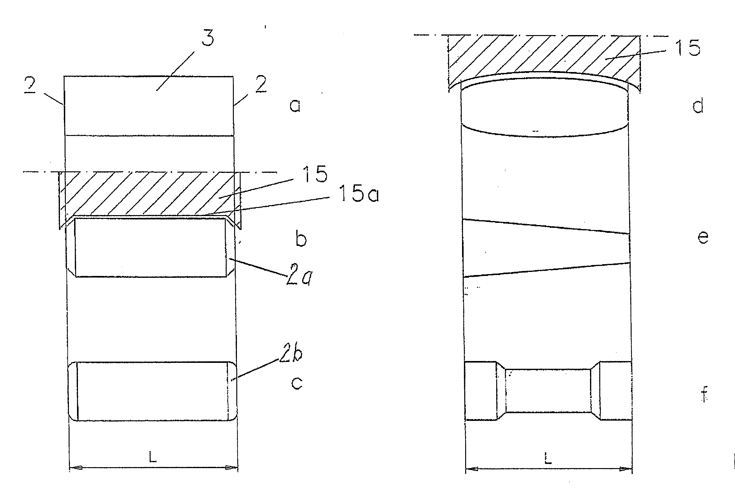
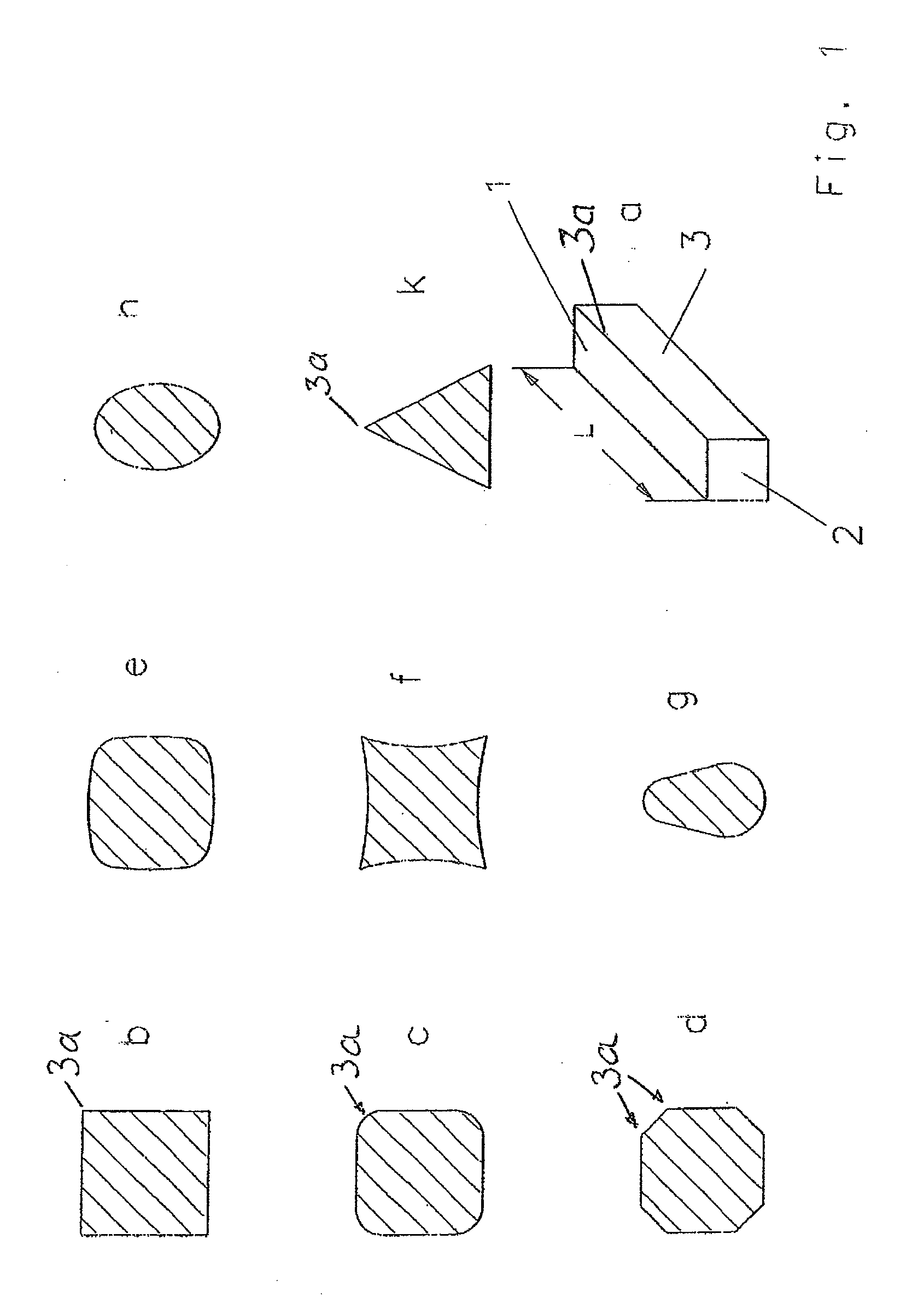
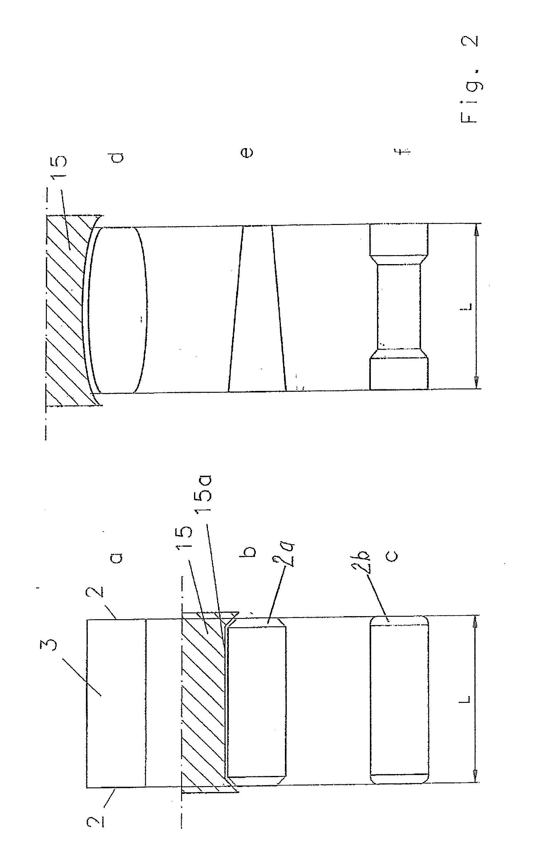
[0050]FIG. 1 provides examples of the shape that the cross-section of the rod-shaped workpiece 1 to be ground can have. In its simplest shape, the rod-shaped workpiece 1 is a block-shaped rod with square end faces 2 and rectangular longitudinal sides 3 that meet in lateral edges 3a (see FIGS. 1a through 1d). One preferred area of application for such rod-shaped workpieces 1 are actuators in mechanical switching or control devices. These control members can have a length L between 10 and 80 mm and a cross-section between 2 and 15 mm; however, this is only an example. Materials for such rod-shaped workpieces 1 are different metals, but also ceramic materials. Depending on the function desired, the cross-section does not have to be a strictly geometrical square (b). Thus, the longitudinal edges can be rounded (c) or provided with flat bevels (d). The square shape can also be varied to include a square with convex surfaces (e) or concave surfaces (f). Furthermore possible are contours h...


PUM

PropertyMeasurementUnit
edge lengthaaaaaaaaaa

Abstract

Short and/or rod-shaped workpieces are completely machined by grinding two parallel end faces and the longitudinal sides of the workpiece with very short cycle times. The grinding machine includes two grinding spindles that are arranged in a tandem arrangement with parallel rotational axes on a shared grinding headstock and that are jointly moved in the X direction. In cooperation with a special holding and transport device for the workpieces, two workpieces are each ground, at least partly concurrently, the end faces of the one workpiece being ground in one machining position and the final non-circular grinding of the exterior contour of a second workpiece occurring in a second machining station, the end faces of the second workpiece having already been ground.

Description

BACKGROUND OF THE INVENTION[0001]The invention relates to a method and a grinding machine for the complete grinding of short and / or rod-shaped workpieces that have a non-circular cross-section that is formed by straight and / or curved lines and that have flat end faces that run parallel to one another and relates to a grinding machine in which two grinding spindles are arranged in tandem and that is particularly suitable for performing the method.[0002]The phrase “short and / or rod-shaped workpieces” means that the only workpieces intended are those that do not require machining with an adjustment of the grinding wheel in the Z direction, e.g. the longitudinal direction of the workpiece, or that require only a minor adjustment in the Z direction, perhaps for producing a bevel in the area of the end faces. Thus the grinding wheels are positioned only in the X direction that is perpendicular thereto. In any case, the workpieces have two end faces that are parallel to one another and one...

Claims


Application Information

Patent Timeline
Patent Type & Authority Applications(United States)
IPC IPC(8): B24B49/00
CPCB24B5/01B24B5/02B24B19/08B24B7/17B24B5/32
Inventor HIMMELSBACH, GEORG
Owner ERWIN JUNKER MASCHNINENFAB
Why Eureka
Try Eureka