Heat exchanger and refrigerant cycle device using the same

a technology of heat exchanger and refrigerant cycle, which is applied in the direction of defrosting, domestic cooling apparatus, etc., can solve the problems of dispersion between the surface of the heat exchanging portion and the ice, and achieve the effect of reducing heat energy

Inactive Publication Date: 2011-08-18
DENSO CORP
View PDF9 Cites 16 Cited by
  • Summary
  • Abstract
  • Description
  • Claims
  • Application Information

AI Technical Summary

Benefits of technology

[0008]The present invention is made in view of the above matters, and it is an object of the present invention to

Problems solved by technology

Furthermore, the thermal deformation member is deformed by a temperature change between a first temperature lower than the predetermined temperature and a second temperature higher than

Method used


Image

  • Heat exchanger and refrigerant cycle device using the same
  • Heat exchanger and refrigerant cycle device using the same
  • Heat exchanger and refrigerant cycle device using the same

Examples


first embodiment

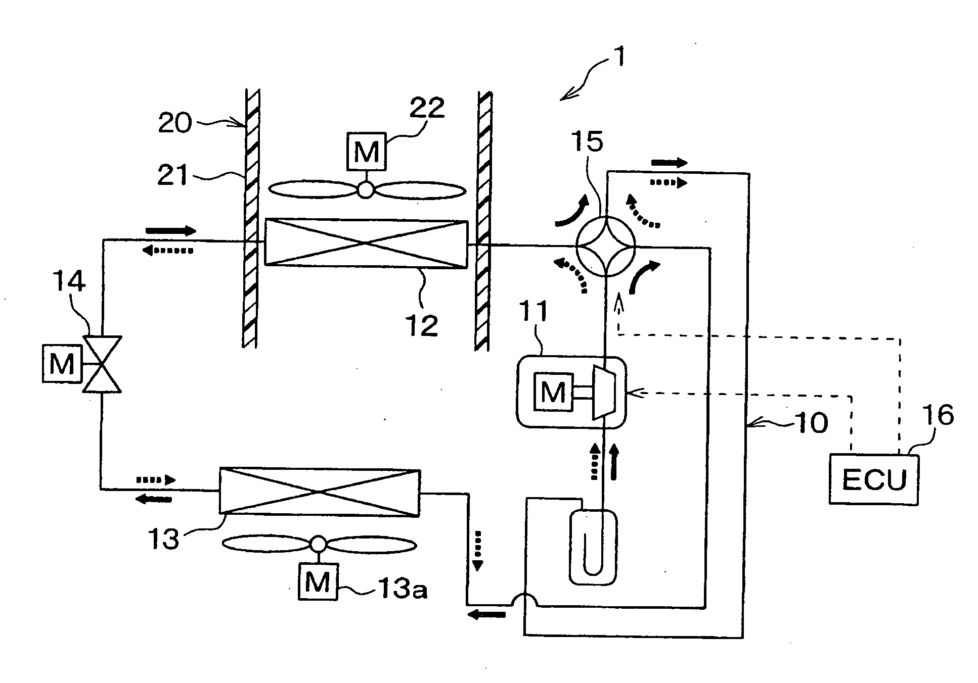
[0033]FIG. 1 is a schematic diagram showing a refrigerant cycle device according to a first embodiment of the invention. In the present embodiment, the refrigerant cycle device is typically used for a vehicle air conditioner 1 mounted to an electrical vehicle (EV) or a hybrid vehicle (HV), for example.

[0034]As shown in FIG. 1, the air conditioner 1 includes a vapor-compression refrigerant cycle 10 and an interior air conditioning unit 20. The refrigerant cycle 10 is configured to be switchable between a cooling operation mode and a heating operation mode.

[0035]The refrigerant cycle 10 includes a compressor 11, an interior heat exchanger 12, an exterior heat exchanger 13, a decompression device 14, a four-way valve 15 and a controller (ECU) 16.

[0036]The compressor 11 is disposed in an engine compartment to draw refrigerant, to compress the drawn refrigerant and to discharge the compressed refrigerant. For example, the compressor 11 is an electrical compressor in which a fixed-displac...

second embodiment

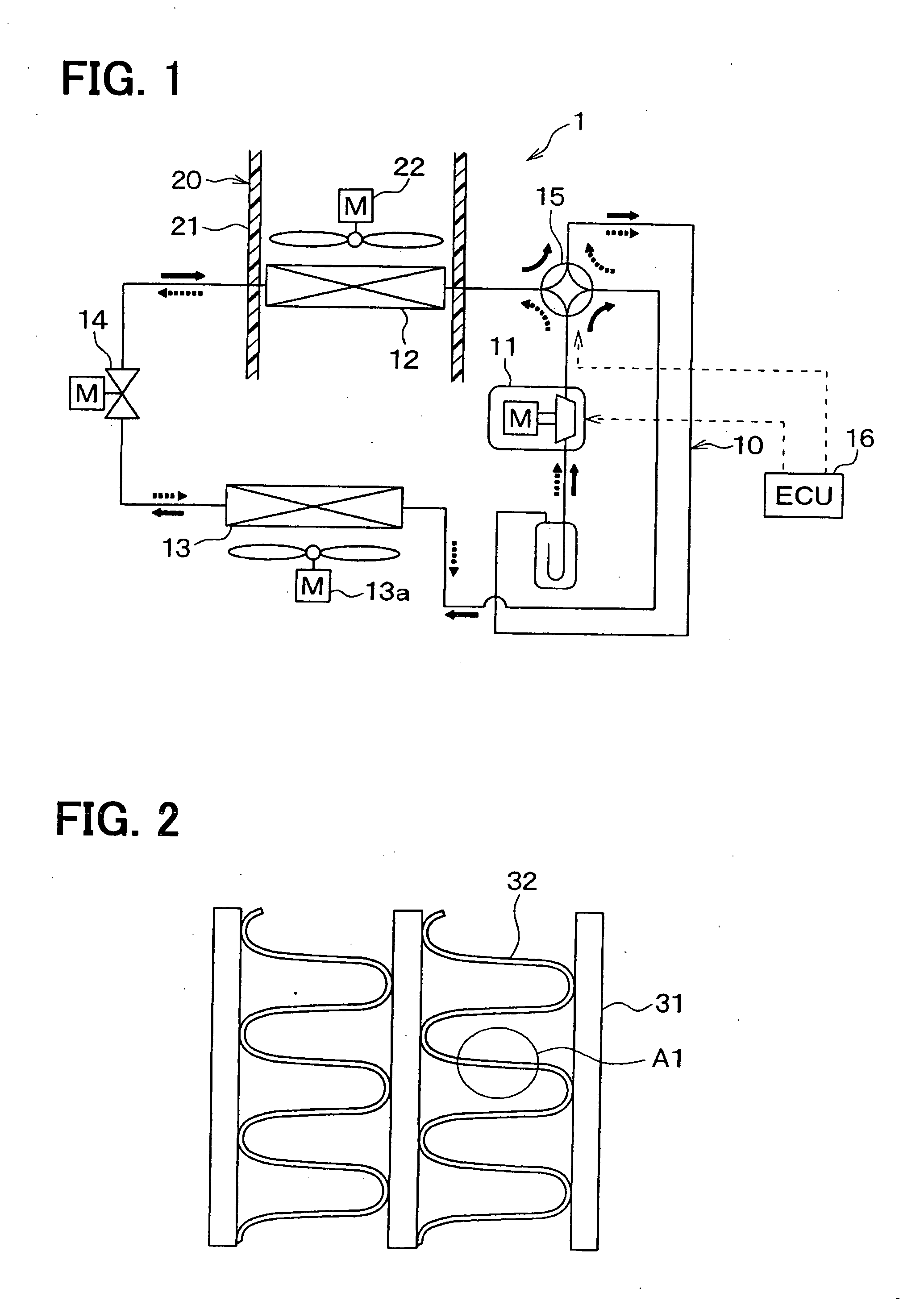
[0087]A second embodiment of the present invention will be described with reference to FIG. 8. FIG. 8 is a schematic perspective view showing thermal deformation members 40 on a surface of a fin 32 used for an evaporator, according to the second embodiment.

[0088]In the second embodiment, as shown in FIG. 8, plural thermal deformation members 40 are arranged in dispersion in the entire range of the surface of the fin 32, to be separated, from each other. Furthermore, a distance L1 between adjacent thermal deformation members 40 at an upstream air side is made larger than a distance L2 between adjacent thermal deformation members 40 at a downstream air side, as shown in FIG. 8.

[0089]In addition, the size of the thermal deformation member 40 located at an upstream air side is made larger than the size of the thermal deformation member 40 located at a downstream air side. The sizes of the thermal deformation members 40 arranged in the air flow direction may be set gradually smaller alon...

third embodiment

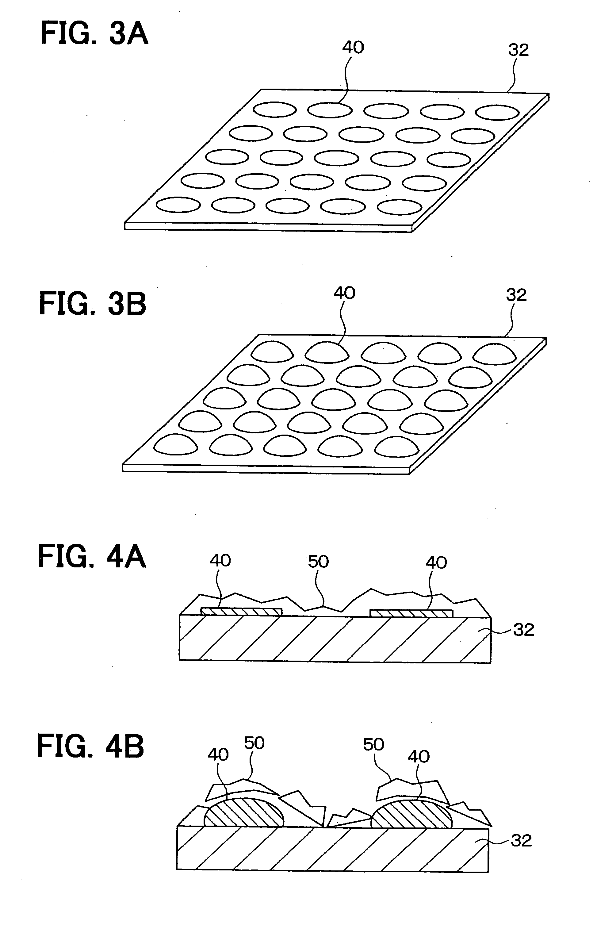
[0093]A third embodiment of the present invention will be described with reference to FIGS. 9A and 9B. FIGS. 9A and 9B are schematically sectional views showing thermal deformation members 40 on the surface of the fin 32 used for an evaporator, according to the third embodiment.

[0094]In the present embodiment, the thermal deformation member 40 is made of a bimetal 43. This bimetal 43 is formed by bonding two-kind metal materials 43a, 43b having different thermal expansion coefficients. The thermal deformation members 40 configured by the bimetal 43 are disposed on the surface of the fin 32, such that the metal material 43a with a low thermal expansion coefficient is positioned outside of the bimetal 43, and the metal material 43b with a high thermal expansion coefficient is positioned to contact the surface of the fin 32.

[0095]Thus, in the temperature range where the surface temperature of the fin 32 is lower than material deformation temperature, the bimetal 43 becomes in a flat sh...


PUM


Abstract

A heat exchanger usable as an evaporator in a refrigerant cycle device includes a heat exchanging portion configured to perform heat exchange between refrigerant and air so as to evaporate the refrigerant. A thermal deformation member is provided in en entire range on a surface of the heat exchanging portion, to be deformed bordering on a predetermined temperature when the surface of the heat exchanging portion is frosted to produce ice. The thermal deformation member is deformed by a temperature change between a first temperature lower than the predetermined temperature and a second temperature higher than the predetermined temperature, to cause distortion between the surface of the heat exchanging portion and the ice when the ice is attached to the surface of the heat exchanging portion. Thus, the ice attached to the surface of the heat exchanging portion can be effectively removed while heat energy for removing the ice can be reduced.

Description

CROSS REFERENCE TO RELATED APPLICATION[0001]This application is based on Japanese Patent Application No. 2010-032229 filed on Feb. 17, 2010, the contents of which are incorporated herein by reference in its entirety.FIELD OF THE INVENTION[0002]The present invention relates to a heat exchanger usable as an evaporator, and a refrigerant cycle device using the same.BACKGROUND OF THE INVENTION[0003]Patent Document 1 (JP Patent No. 4269660) describes regarding the technique for easily removing frost attached to an evaporator for a refrigerant cycle device.[0004]In the Patent Document 1, a surface portion A, in which the frosted ice is easy to be melted, and a surface portion B, which is difficult to be frosted, are arranged to be dispersed on the surface of each plate fin of the evaporator. Thus, in a defrosting operation, ice attached to the surface portion A can be easily separated from the surface portion A by melting, and thereby the ice attached to the surface portion B can be also ...

Claims


Application Information

Patent Timeline
IPC IPC(8): F25D21/02F25B49/02F25B41/00
CPCB60H1/00335F28D2021/0071F28G13/00F28F21/08F28F17/00F25B2600/01F25B2400/0403F25B47/025F25B13/00F25B2600/0253F25B2313/0315F25B39/02
Inventor SUZUKI, YOSHINOBUTAKEDA, KODAIHIROSE, MASAAKI
Owner DENSO CORP
Why Eureka
Try Eureka