Novel aliphatic polycarbonate

a polycarbonate and aliphatic technology, applied in the field of aliphatic polycarbonate, can solve the problems of large residual carbon and adversely affect the performance of products, and achieve the effect of reducing heat energy

Inactive Publication Date: 2020-07-30
NAT UNIV CORP TOKYO UNIV OF AGRI & TECH +1
View PDF0 Cites 0 Cited by
  • Summary
  • Abstract
  • Description
  • Claims
  • Application Information

AI Technical Summary

Benefits of technology

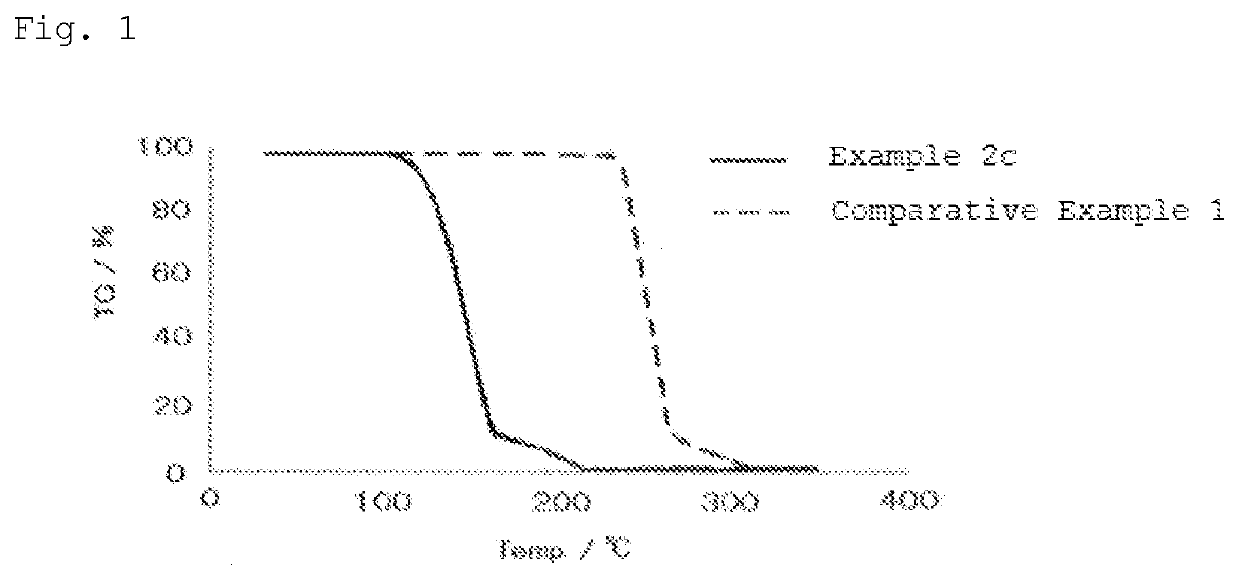
[0011]The aliphatic polycarbonate according to the present invention is thermally decomposable at a relatively low temperature. Thus, when used as a thermally decomposable binder, the aliphatic polycarbonate can be thermally decomposed (dewaxed) at a low temperature, which accordingly enables significant reduction in heat energy. In addition, since the aliphatic polycarbonate can be thermally decomposed (dewaxed) even in a non-oxidative atmosphere, the aliphatic polycarbonate can be dewaxed in a non-oxidative atmosphere, even when containing inorganic particles that may be reacted with oxygen.

Problems solved by technology

However, these resins have a decomposition temperature of 400° C. or higher; and an insufficient dewaxing temperature results in a large amount of residual carbon, which may adversely affect the performance of products.

Method used


Image

  • Novel aliphatic polycarbonate
  • Novel aliphatic polycarbonate
  • Novel aliphatic polycarbonate

Examples


production example 1

Complex Catalyst

[0126]A 100-mL eggplant flask equipped with a stirrer and a gas inlet tube was charged with 0.30 g (8.3 mmol) of N,N′-bis(3,5-di-tert-butylsalicylidene)-1,2-cyclohexanediaminocobalt (produced by Aldrich), 0.10 g (8.5 mmol) of pentafluorobenzoic acid, and 13.3 g of dichloromethane; and the contents were stirred for 19 hours while introducing air thereinto. The volatile component was distilled off under reduced pressure, thus obtaining a cobalt complex represented by the above formula (4-3) as a brown solid (yield amount: 0.35 g, yield rate: 88%).

production example 2a

ry Amino Group-Containing Epoxide Protected by a Benzyl Group

[0127]

[0128]A 50-mL Schlenk flask containing a magnetic stirring bar was charged with 865 mg (6.3 mmol) of potassium carbonate. Then, after the internal system was replaced with an argon atmosphere, the system was charged with 9.4 g of N,N-dimethylformamide (DMF), 0.72 g (5.3 mmol) of N-benzyl-N-ethylamine, and 8.5 g (62 mmol) of epibromohydrin. After the resulting mixture was stirred at ordinary temperature for 48 hours, and extracted 3 times with 13.3 g of dichloromethane, the combined organic layers were washed twice with 30 g of saturated brine, and once with ion exchanged water. The organic layers were concentrated under reduced pressure, and the obtained residue was purified by silica gel column chromatography (n-hexane / ethyl acetate=4 / 1 (v / v), Rf=0.53) to give a colorless oily N-benzyl-N-oxiranylmethyl-N-ethylamine (yield amount: 0.93 g, yield rate: 91%).

[0129]The structure of the obtained compound was identified by...

production example 2b

[0131]The operation was carried out in the same manner as in Production Example 2a, except that N-benzyl-N-isopropylamine was used as amine, to give colorless oily N-benzyl-N-oxiranylmethyl-N-isopropylamine (yield amount: 1.00 g, yield rate: 92%).

[0132]The structure of the obtained compound was identified by 1H-NMR.

[0133]1H-NMR (CDCl3) δ=7.30-7.20 (m, 5H), 3.66 (s, 2H), 2.96 (m, 1H), 2.77 (m, 1H), 2.65-2.61 (m, 2H), 2.40-2.35 (m, 2H), 1.05 (d, 6H) ppm.


PUM

PropertyMeasurementUnit
decomposition temperatureaaaaaaaaaa
temperatureaaaaaaaaaa

Abstract

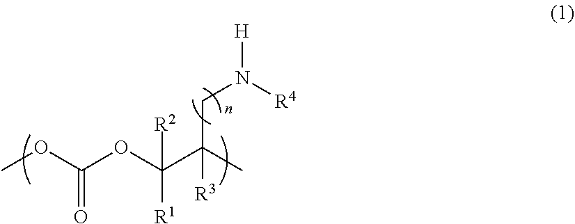
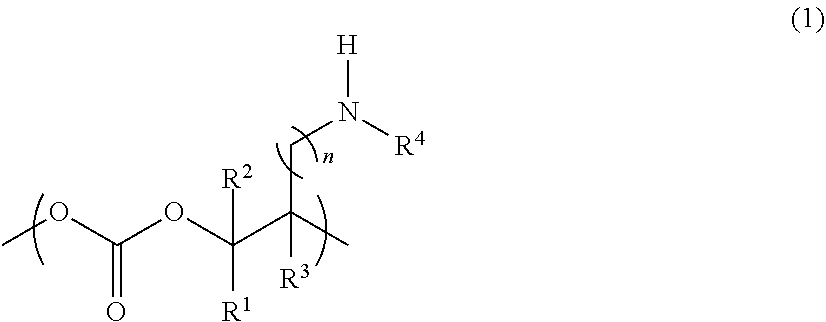
The present invention provides an aliphatic polycarbonate that can be thermally decomposed (dewaxed) at a relatively low temperature. The aliphatic polycarbonate comprises a constituent unit represented by formula (1):
wherein R1, R2, and R3 are identical or different, and each represent a hydrogen atom, a substituted or unsubstituted alkyl group having 1 to 15 carbon atoms, or a substituted or unsubstituted aryl group having 6 to 20 carbon atoms; R4 represents a substituted or unsubstituted alkyl group having 1 to 20 carbon atoms, or a substituted or unsubstituted aryl group having 6 to 20 carbon atoms; and n is an integer of 0 to 3.

Description

TECHNICAL FIELD[0001]The present invention relates to an aliphatic polycarbonate having a novel structure, a thermally decomposable binder comprising the aliphatic polycarbonate, a slurry composition comprising the aliphatic polycarbonate, and the like.BACKGROUND ART[0002]A slurry composition obtained by dispersing fine particles of an inorganic compound in a solvent together with a binder resin is used for obtaining sintered bodies having various shapes. For example, a slurry composition comprising a binder resin and fine particles of metals, such as silver, copper, and nickel, is used for forming a circuit on a substrate or forming an electrode. A slurry composition comprising a binder resin and fine particles of ceramics, such as alumina, zirconia, barium titanate, and silicon carbide, is used for forming electronic devices.[0003]The binder resin is removed by thermal decomposition in a dewaxing step after molding. As the binder resin, cellulose resin, butyral resin, acrylic resi...

Claims


Application Information

Patent Timeline
Patent Type & Authority Applications(United States)
IPC IPC(8): C08G64/02
CPCC08G64/0241C08G64/02C08K3/00C08L69/00C08K3/013C08K2003/2227C08G64/34C08K2003/0806
Inventor NAKANO, KOJINISHIOKA, KIYOSHI
Owner NAT UNIV CORP TOKYO UNIV OF AGRI & TECH
Why Eureka
Try Eureka