Gas adsorption and separation apparatus and applications thereof

a separation apparatus and gas adsorption technology, applied in the direction of chemistry apparatus and processes, separation processes, dispersed particle separation, etc., can solve the problems of malodor intrusion into the surrounding environment, the concentration ratio is greatly reduced, and the emission concentration of treated waste gas exceeds the standard seriously, so as to reduce the energy consumption, the effect of low desorption gas capacity and high concentration of organic pollutants

Pending Publication Date: 2021-09-02
SHANGHAI SHENCHENG ENVIRONMENTAL PROTECTION EQUIP ENG
View PDF3 Cites 1 Cited by
  • Summary
  • Abstract
  • Description
  • Claims
  • Application Information

AI Technical Summary

Benefits of technology

[0033]According to the gas adsorption and separation apparatus of the present invention, in the operation process of the whole apparatus, which comprises an adsorption process, a desorption process and a cooling and thermal regeneration process, a continuous and complete counterflow mass and heat transfer process often adopted in the chemical engineering field and thermal engineering field is implemented through the relative movement between an adsorbent and a working gas. The low capacity of the desorption gas and the high concentration of organic pollutants also reduce the energy consumption when they are destroyed by fire power or recovered by using an agglutination method. The complete counterflow heat transfer in the thermal regeneration process reduces the heat energy that must be consumed in the thermal regeneration process of the adsorbent.

Problems solved by technology

In extreme situations, all adsorbents should reach saturated adsorption, which will inevitably lead to the emission concentration of the treated waste gas exceeding the standard seriously.
In extreme situations, all adsorbents in the adsorption bed should be completely desorbed, which inevitably results in that the concentration ratio is greatly reduced until there is no concentration effect at all, or even the process becomes a dilution process.
For example, in the field of VOC waste gas treatment, flue gas generated in the casting process of a metal casting resin mold has special characteristics, and its main adverse effect is the malodor intrusion to factory staff and the surrounding environment.
Among existing ordinary treatment processes for treating VOC or conventional organic malodorous gases, photocatalytic and low-temperature plasma removal have low efficiency and poor effects.
Due to the complex composition of the gas producing malodor, the rotary adsorber or the regenerative fixed-bed adsorber has poor adsorption effects.
In order to ensure the adsorption effect, a very long adsorption process has to be used, which significantly increases costs of adsorption and desorption.
In addition, there is also the problem of rapid failure of the adsorbent due to being covered by macromolecular colloids.
It is difficult to eliminate the macromolecular colloids through low-temperature catalytic combustion, and the adsorbent is likely to be covered and failed, while when direct combustion, regenerative combustion or catalytic combustion is used, the calorific value of combustible gas contained in flue gas itself is extremely low due to a huge air flow, making the fuel consumption economically unbearable.
In addition, there are some problems, for example, combustible condensate is accumulated in a flue gas collection pipeline, and easily causes a sudden fire when dripping onto a high-temperature casting body.
During incineration, a large amount of smoke and organic waste gas will be generated due to incomplete combustion, which is a significant air pollution process.

Method used


Image

  • Gas adsorption and separation apparatus and applications thereof
  • Gas adsorption and separation apparatus and applications thereof
  • Gas adsorption and separation apparatus and applications thereof

Examples


embodiment 1

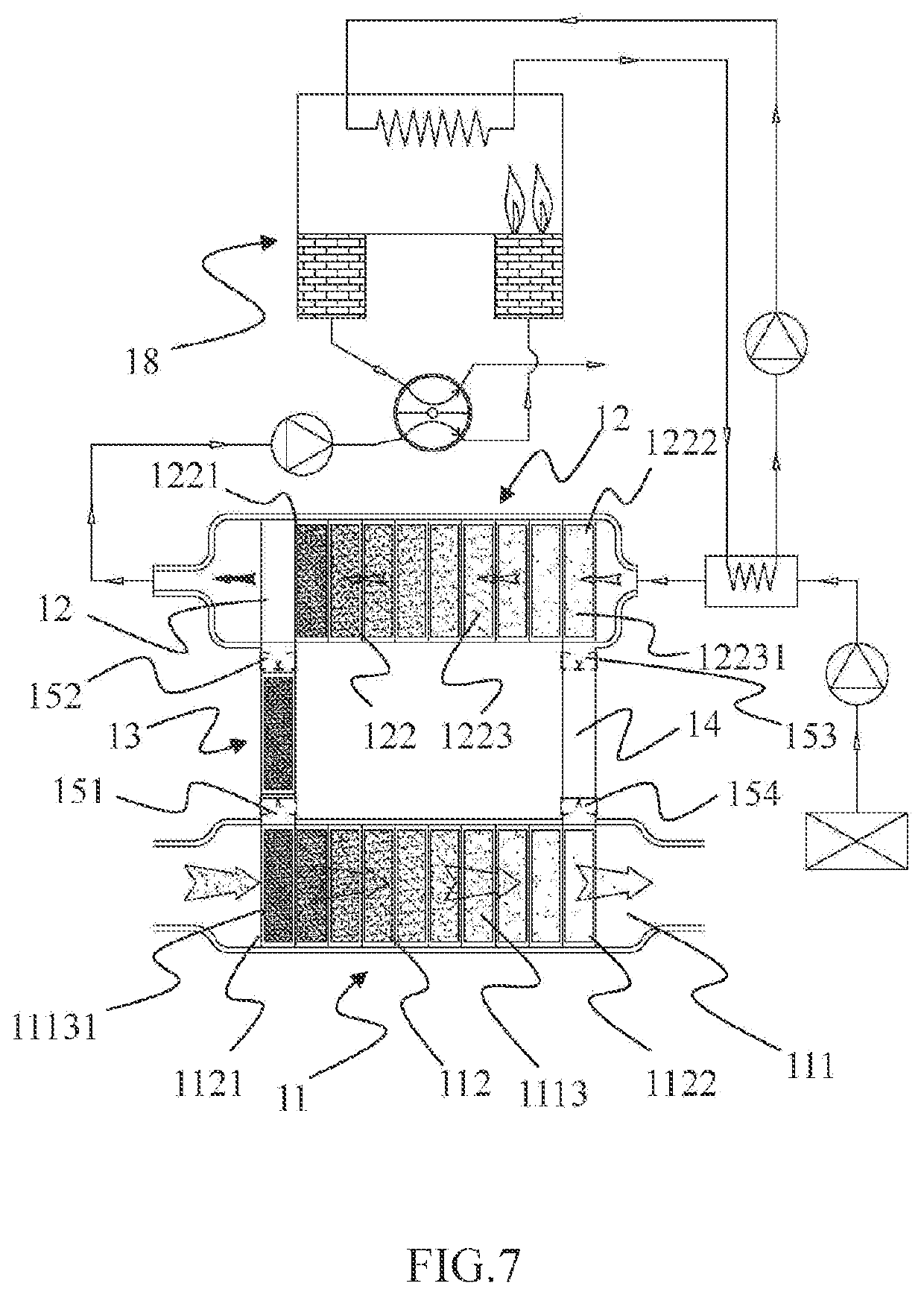
[0064]FIGS. 7 and 8 show a unit moving type gas adsorption and separation apparatus.

[0065]Referring to FIG. 7, the apparatus comprises an adsorption apparatus 11, a desorption apparatus 12, a saturation transition chamber 13 and a regeneration transition chamber 14. The adsorption apparatus 11 comprises an adsorption chamber 111 and an adsorption series 112 accommodated in the adsorption chamber. The adsorption series 112 comprises a head end 1121, a tail end 1122, and two or more adsorption units 1113. The unit at the head end 1121 that has completed saturated adsorption is a saturated adsorption unit 11131.

[0066]The desorption apparatus 12 comprises a desorption chamber 121 and a desorption series 122 accommodated in the desorption chamber. The desorption series 122 comprises a saturation end 1221, a regeneration end 1222 and two or more desorption units 1223. The unit at the regeneration end 1222 that has completed desorption is a regenerated adsorption unit 12231,

[0067]Two ends ...

embodiment 2

[0073]FIGS. 9 and 10 show a unit supply and recovery type gas adsorption and separation apparatus.

[0074]One of the important conditions for the specific application of the gas adsorption and separation apparatus shown in Embodiment 2 is that the flow rate of waste gas to be treated and the concentration of organic pollutants are substantially stable, because thermal desorption needs to use the organic pollutants in the waste gas as heating fuel to keep a substantially stable high-temperature environment. if the waste gas is discharged intermittently or the flow rate and the concentration fluctuate greatly, a de-adsorption process will be adversely affected, and it is generally necessary to add additional supplementary fuel, The unit supply and recovery type gas adsorption and separation apparatus disclosed in Embodiment 2 can adapt to this situation very well.

[0075]The specific solution of the unit supply and recovery type gas adsorption and separation apparatus is that an adsorptio...

embodiment 3

[0076]FIG. 11 and an apparatus for adsorption and separation of a thermal regeneration gas.

[0077]In the gas adsorption and separation apparatus shown in Embodiment 1, the regenerated adsorption unit that has completed desorption is still in a. high-temperature state when it enters the regeneration chamber through the transition chamber and is added to the adsorption series. Although a large flow of polluted air which has been substantially adsorbed quickly takes away its heat and there is no significant impact on the adsorption process, the loss of heat energy of the system is caused. This has a certain negative impact on reduction of energy consumption, which is one of the original purposes of the apparatus according to the invention.

[0078]The technical solution to overcome this technical disadvantage is to replace the regeneration transition chamber 14 in Embodiment 1 with a thermal regeneration apparatus 17, and transfer, to the adsorption series, the heat contained in the high-t...


PUM


Abstract

Provided is a gas adsorption and separation apparatus, comprising an adsorption functional module (01) and a further functional module (02), wherein a main functional portion of the adsorption functional module (01) is an adsorption series (011) composed of two or more adsorption units (09) arranged in sequence; the adsorption series (011) comprises a head end (0111) and a tail end (0112); a gas to be separated passes through the adsorption series (011) in a direction from the head end (0111) to the tail end (0112); when reaching a preset degree of saturation adsorption of the adsorbate gas, the adsorption unit (09) located at the head end (0111) is detached from the adsorption series (011) and enter the further functional module (02) comprising a desorption apparatus (021), and sequentially re-enters the adsorption series (011) from the tail end (0112) after a further process treatment including a desorption treatment is completed; and each adsorption unit (09) is an adsorptive fixed bed which is composed of an adsorbent and a mechanical support structure and has a proper mechanical strength and a good permeability, the adsorption unit (09) which has completed saturated adsorption is referred to as a saturated adsorption unit (091), and the adsorption unit (09) which has completed desorption and regeneration is referred to as a regenerated adsorption unit (092).

Description

CROSS REFERENCE TO RELATED APPLICATIONS[0001]The present application claims the priority of Chinese patent application 201810794980.5 filed on Jul. 9, 2018 and Chinese patent application 201811144414.6 filed on Sep. 20, 2018, and these earlier applications are incorporated herein by reference.TECHNICAL FIELD[0002]The present invention relates to a gas adsorption and separation apparatus, and in particular, to an apparatus for concentrating organic waste gas pollutants by using an adsorption method, and specific applications thereof.BACKGROUND ART[0003]Gas concentration technologies using an adsorption method have been more and more widely used in the field of atmospheric volatile organic compound (VOC, referred to as organic pollutants for short) pollution control. Common gas adsorption and separation apparatuses include rotary adsorbers and regenerative fixed-bed adsorbers. The ultimate goal of design of these gas adsorption and separation apparatuses is to concentrate waste gas of...

Claims


Application Information

Patent Timeline
Patent Type & Authority Applications(United States)
IPC IPC(8): B01D53/04B01D53/047
CPCB01D53/0438B01D53/0462B01D53/0476B01D2259/402B01D2258/0283B01D2259/40005B01D53/0446B01D53/08B01D53/0407B01D53/047B01D2257/70Y02A50/20
Inventor ZHANG, CHUANZHONG
Owner SHANGHAI SHENCHENG ENVIRONMENTAL PROTECTION EQUIP ENG
Why Eureka
Try Eureka