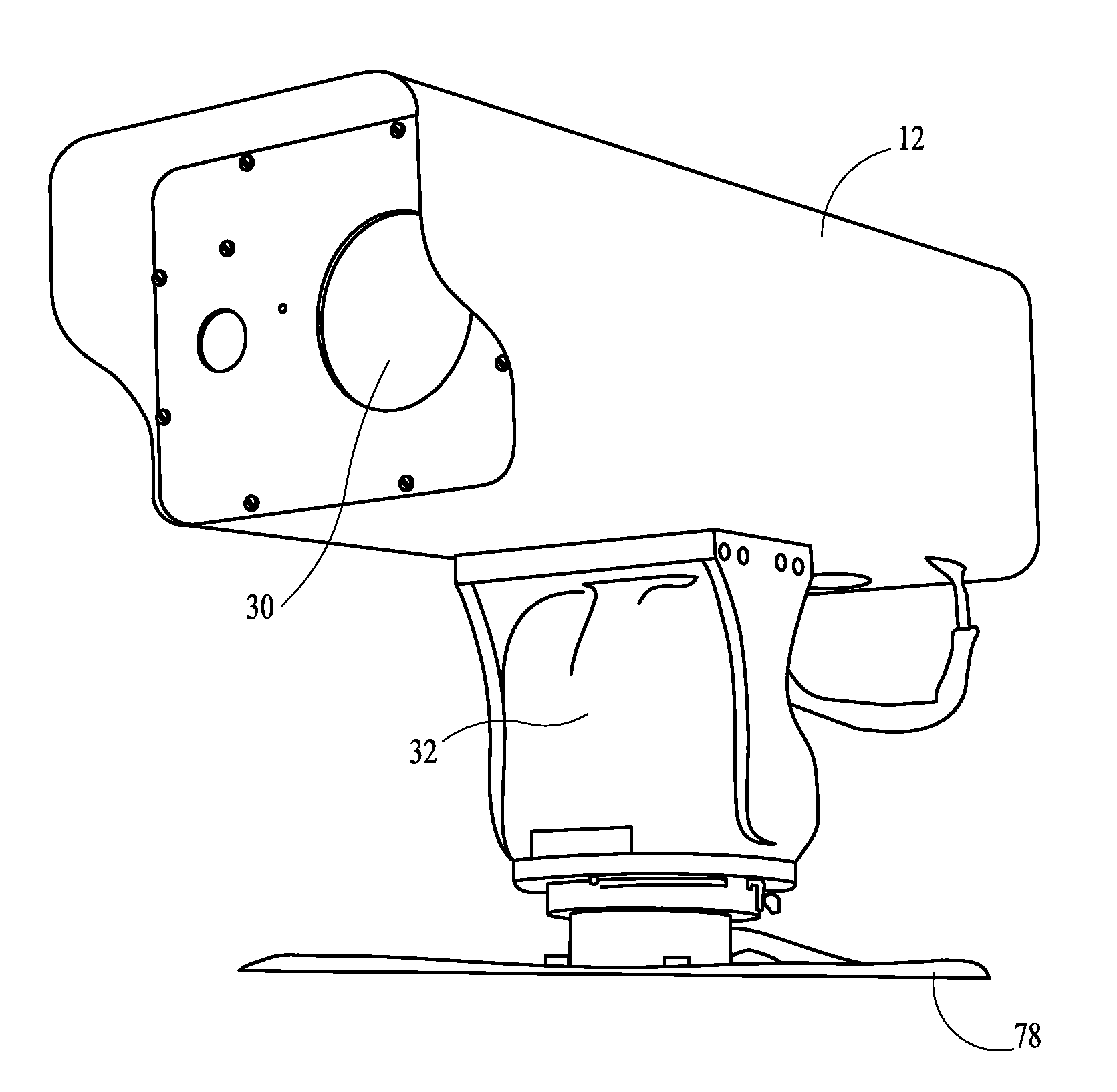
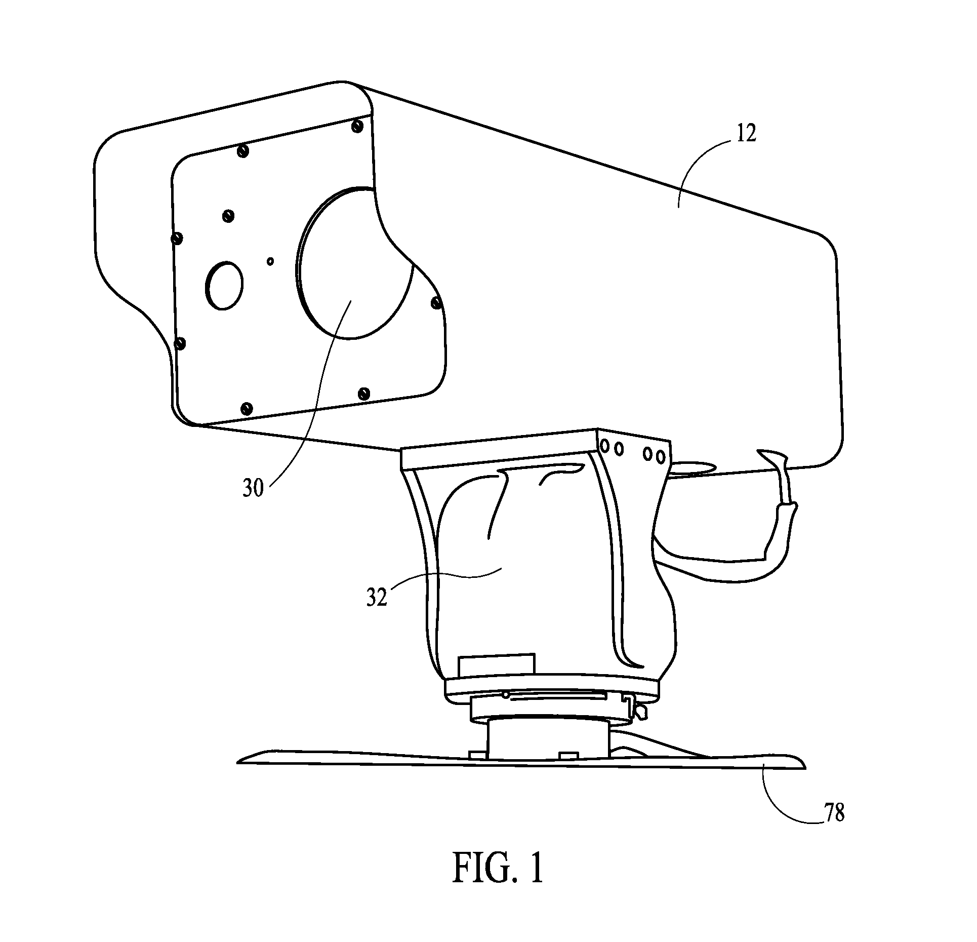
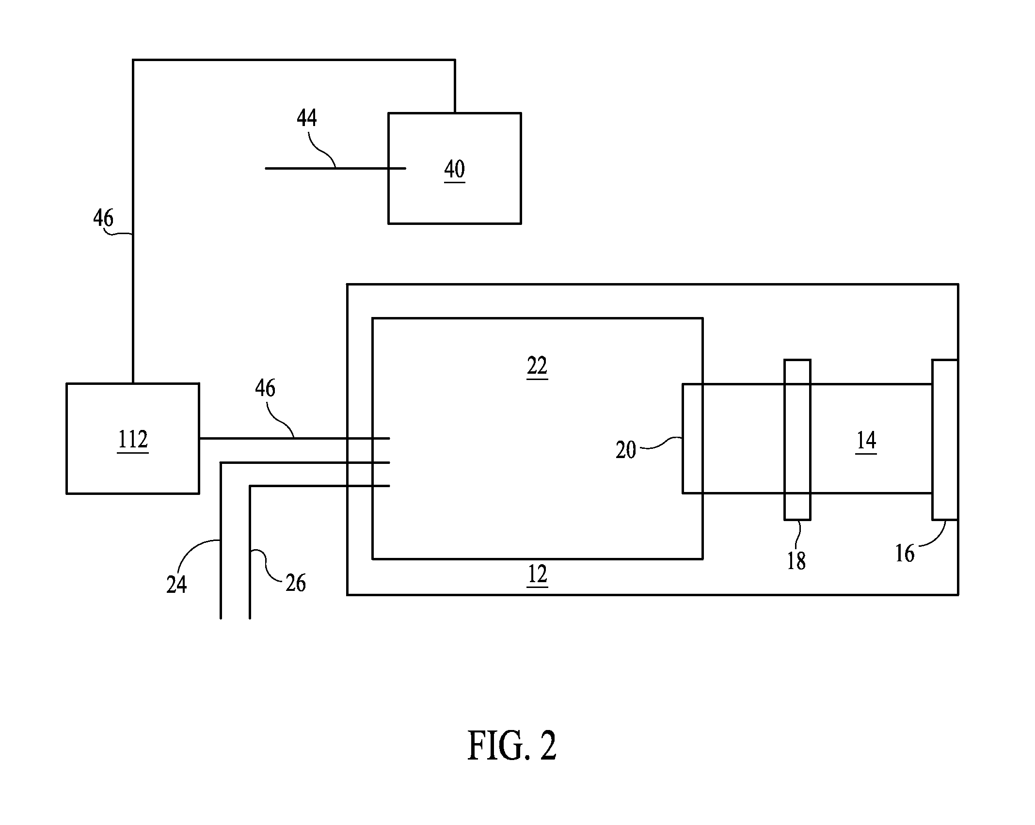
Long Range Day/Night Surveillance Video Camera

a video camera and long-range technology, applied in the field of video cameras, can solve the problems of high power level, high cost of gallium arsenide devices, and the possibility of unintended retinal damage of lasers with coherent output near 900 nm, and achieve the effect of high light suppression and high light suppression

Inactive Publication Date: 2011-08-18
MORGAN ARTHUR C
View PDF7 Cites 66 Cited by
  • Summary
  • Abstract
  • Description
  • Claims
  • Application Information

AI Technical Summary

Benefits of technology

[0045]In another preferred embodiment, the camera system wherein the dimensions of the system casing are 50.5 mm wide, 50.5 mm high and 115 mm long.
[0046]In a more preferred embodiment, a high resolution day / night video camera system, comprising: a video camera with a zoom lens wherein the focal length of the zoom lens is 12.5-750 mm zoom with internal digital double that functions at 20-1500 mm.; wherein the iris range of the zoom lens is 4.6˜720; wherein the electronic shutter speed range is between 1 / 50 and 1 / 120,000 second; wherein the signal to noise ratio is between 52 dB and 60 dB; a ½ inch CCD image sensor; motion detecting capability; selectable features of negative imaging, 2× digital zoom, mirroring, and adjustable automatic gain control; a high resolution image processing component delivering resolution up to 520 television lines (TVLs) using either a NTSC or PAL television system; said camera system providing total pixels of 410K×470K pixels; wherein the system further provides motion detecting capability; wherein the system further provides selectable features of negative imaging, mirroring, and adjustable automatic gain control; wherein the system further provides adjustable high light suppression capability; wherein the video camera remains operable between −20° C. and 50° C., and at up to 85% relative humidity; a light sensitivity processing component providing sensitivity of 0.08 Lux at F1.2, in daytime mode and 0.008 Lux at F1.2 in nighttime mode; a backlight compensation (BLC) image processing component for image enhancement; said camera mounted on a heavy duty pan / tilt motor system controlled by an integrated RS-485 pan and tilt controller communication protocol or other similar protocol; said heavy duty pan and tilt motor system enabling the video camera to move axially across horizontal range of a vertical axis of from about 0 to about 360 degrees and to move axially across a vertical range of a horizontal axis of from about −45 degrees to about +45 degrees; an infrared laser illuminator operating at approximately the 808 nanometer wavelength; wherein the laser infrared illuminator capable of operating at a temperature between 18 degrees C. and 30 degrees C.; wherein the laser infrared illuminator is a diode-pumped solid state laser infrared illuminator; said camera system operating within the light range of 3200° K to 10000° K; and said camera system wherein the dimensions of the system casing are 50.5 mm wide, 50.5 mm high and 115 mm long.
[0047]In another preferred embodiment, the video camera system described in the paragraph above, further comprising wherein the laser infrared illuminator comprises: dimensions of 165 mm×74 mm×78 mm; output power of 2400 mw; TTL modulation analogy; beam quality of (M2) less than 3; beam ellipticity of less than 10%; pointing drift of less than 0.2 mrad; power stability of less than 5% @ 4 hours; beam diameter of less than 3 mm at the output mirror; beam divergence of less than 1.2 mrad; a warm up time of less than 10 minutes; a lifetime of over 10,000 hours of usage; and electrical requirements of 24VAC / 6 amps.
[0048]In a more preferred embodiment, a high resolution day / night video camera system, comprising: a video camera with a zoom lens wherein the focal length of the zoom lens is 12.5-750 mm zoom with internal digital double that functions at 20-1500 mm; wherein the iris range of the zoom lens is 4.6˜720; wherein the electronic shutter speed range is between 1 / 50 and 1 / 120,000 second; wherein the signal to noise ratio is between 52 dB and 60 dB; a ½ inch CCD image sensor; motion detecting capability; selectable features of negative imaging, 2× digital zoom, mirroring, and adjustable automatic gain control; a high resolution image processing component delivering resolution up to 520 television lines (TVLs) using either a NTSC or PAL television system; wherein the image provided totals of 410K×470K pixels; wherein the system further provides motion detecting capability; wherein the system further provides selectable features of negative imaging, mirroring, and adjustable automatic gain control; wherein the system further provides adjustable high light suppression capability; wherein the video camera remains operable between −20° C. and 50° C., and at up to 85% relative humidity; a light sensitivity processing component providing sensitivity of 0.08 Lux at F1.2, in daytime mode and 0.008 Lux at F1.2 in nighttime mode; a backlight compensation (BLC) image processing component for image enhancement; said camera mounted on a heavy duty pan / tilt motor system controlled by an integrated RS-485 pan and tilt controller communication protocol or other similar protocol; said heavy duty pan and tilt motor system enabling the video camera to move axially across horizontal range of a vertical axis of from about 0 to about 360 degrees and to move axially across a vertical range of a horizontal axis of from about −45 degrees to about +45 degrees; an infrared laser illuminator operating at approximately the 808 nanometer wavelength; wherein the laser infrared illuminator capable of operating at a temperature between 18 degrees C. and 30 degrees C.; wherein the laser infrared illuminator is a diode-pumped solid state laser infrared illuminator; operating within the light range of 3200° K to 10000° K; said camera system wherein the dimensions of the system casing are 50.5 mm wide, 50.5 mm high and 115 mm long; wherein a tubular axial unit is built within the PTZ support to contain cables; wherein the camera is mounted on a metal platform comprising stabilizing springs; wherein all components containing cables, circuitry or other elements susceptible to water damage are sealed with water-resistant rubber or composite seals; wherein the camera lens is mounted behind a protective, transparent and shatter-resistant plastic shield; wherein the power supply is connected to the system via a battery backup device capable of providing power to the unit for at least 30 minutes in the event of power failure; wherein the PTZ controller further comprises a DRAM computer controller with no disc or other moving parts; said camera system, wherein the PTZ controller further comprises a GPS coordinates computer capable of wireless communications with additional remote camera systems; said camera system, wherein the PTZ controller includes a wireless radio transmitter / receiver to enable a user to operate the system from a remote location using a wireless-enabled laptop computer or similar device containing appropriate controller software; and wherein the PTZ controller includes one or more remote plug-in ports to enable a user to operate the system from such port using a laptop computer or similar device containing appropriate controller software.

Problems solved by technology

Gallium arsenide devices are efficient but costly at high power levels.
In addition, the lasers with coherent output near 900 nm present the possibility of unintended retinal damage.
The lamps generate substantial incoherent light, and while eye-safe and less costly, suffer from poor efficiency in the near-infrared.
In the case of the xenon lamp significant energy is also lost to ultraviolet emissions (also not used).
The low efficiency of the lamps leads to large (heavy) batteries and limited lamp life due to high temperature operation and reactive plasma constituents.
Camera systems taught by the prior art tend to incorporate many interconnected components, for example, using multiple illuminators and types of illuminators, that adversely impact system portability and the effective horizontal turning radius of the camera.
Additionally, the mechanical complexity of systems containing many different components increase the likelihood of breakdowns due to (a) poor environmental conditions, (b) problems with wired and wireless connectivity, (c) mechanical motion and (d) the sheer number of components relied upon for system operations.
The complicated nature of camera systems disclosed in prior art, including the use of multiple illumination devices in any given system, also adversely affects the affordability of such systems and tends to require larger power plants and more robust power delivery systems.

Method used


Image

  • Long Range Day/Night Surveillance Video Camera
  • Long Range Day/Night Surveillance Video Camera
  • Long Range Day/Night Surveillance Video Camera

Examples


Embodiment Construction

Definitions

[0054]The following definitions are provided as an aid to understanding the detailed description of the present invention.

[0055]A charge-coupled device (“CCD”) is an analog shift register that enables the transportation of analog signals (electric charges) through successive stages (capacitors), controlled by a clock signal. Charge-coupled devices can be used as a form of memory or for delaying samples of analog signals. Today, they are most widely used in arrays of photoelectric light sensors to serialize parallel analog signals.

[0056]Dynamic random access memory (“DRAM”) is a type of random access memory that stores each bit of data in a separate capacitor within an integrated circuit. Since real capacitors leak charge, the information eventually fades unless the capacitor charge is refreshed periodically. Because of this refresh requirement, it is a dynamic memory as opposed to SRAM and other static memory. The advantage of DRAM is its structural simplicity: only one t...


PUM


Abstract

This invention relates to video cameras and, more specifically, to a high-resolution day/night video camera with a long lens, fast optics and pan/tilt/zoom electronics, coupled with a diode-pumped solid state laser illuminator for long range low light illumination. Potential applications include ports, borders, pipelines, power stations, communication transmitters and prisons.

Description

STATEMENT REGARDING FEDERALLY SPONSORED RESEARCH OR DEVELOPMENT[0001]No federal government funds were used in researching or developing this invention.CROSS REFERENCE TO RELATED APPLICATIONS[0002]Not applicable.NAMES OF PARTIES TO A JOINT RESEARCH AGREEMENT[0003]Not applicable.REFERENCE TO A SEQUENCE LISTING[0004]Not applicable.BACKGROUND[0005]1. Field of the Invention[0006]This invention relates to video cameras and, more specifically, to a high-resolution day / night video camera with a long lens, fast optics and pan / tilt / zoom electronics, coupled with a diode-pumped solid state laser illuminator for long range low light illumination. Potential applications include ports, borders, pipelines, power stations, communication transmitters and prisons.[0007]2. BACKGROUND OF THE INVENTION[0008]Private companies, government entities and individuals use electronic surveillance systems to remotely monitor areas for providing security. In furtherance of providing general security requirements ...

Claims


Application Information

Patent Timeline
Patent Type & Authority Applications(United States)
IPC IPC(8): H04N7/18
CPCH04N5/2251H04N5/2256H04N5/332H04N5/23296H04N5/232H04N23/50H04N23/56H04N23/69H04N23/11H04N23/695
Inventor MORGAN, ARTHUR C.
Owner MORGAN ARTHUR C
Why Eureka
Try Eureka