Light-shielding film for optical element and optical element having light-shielding film

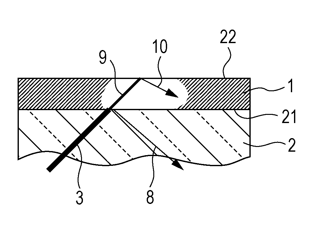
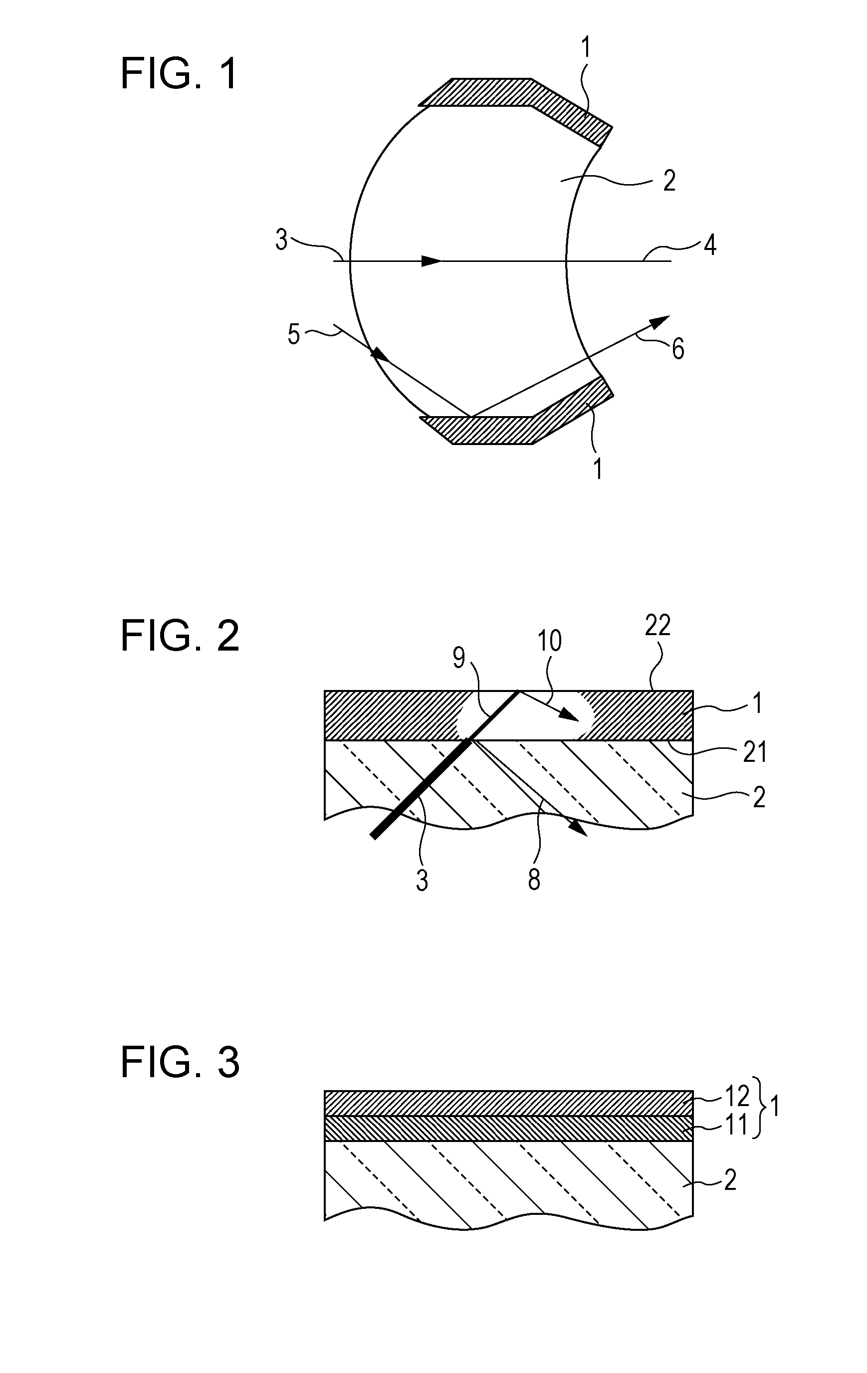
a technology of light shielding film and optical element, which is applied in the direction of spectral modifiers, spectacles/goggles, synthetic resin layered products, etc., can solve the problems of insufficient inhibition of reflection at the interface between the lens and the light shielding film, increase in first reflected light b>8/b>, etc., to achieve the reduction of the design clearance between the lens and the lens barrel, the effect of reducing the size of the lens and improving performan

Inactive Publication Date: 2011-08-18
CANON KK
View PDF7 Cites 37 Cited by
  • Summary
  • Abstract
  • Description
  • Claims
  • Application Information

AI Technical Summary

Benefits of technology

[0006]FIG. 2 is a schematic view illustrating how inner-surface-reflected light travels. As shown in FIG. 2, incident light 3 travels in the lens 2 and becomes first reflected light 8 at the interface 21 with the light-shielding film 1. The transmitted light 9 traveled in the light-shielding film 1 becomes second reflected light 10 at the interface 22 between the light-shielding film 1 and air. Therefore, in the inner-surface reflection, the first reflection light 8 and the second reflection light 10 are involved.
[0007]Recently, along with a reduction in lens size and an improvement in performance, the designed clearance between a lens and a lens barrel has been reduced. Accordingly, if a light-shielding film for optical element has a thickness that is equivalent to those of existing films, since the clearance is small, the lens may not be incorporated into a lens barrel. Therefore, in order to set a lens provided with a light-shielding film into a narrow clearance, the light-shielding film for optical element needs to be reduced in the thickness. In addition, a thinner light-shielding film can decrease the stress, resulting in a reduction in deformation of the lens.
[0008]Japanese Patent Publication No. 47-32419 describes an example of the light-shielding film that absorbs light with coal tar, carbon black, and dye while improving the refractive index with the coal tar. Japanese Patent Laid-Open No. 2007-183444 describes an example of the light-shielding film that absorbs light with coal tar and dye while improving the refractive index with the coal tar. Japanese Patent Laid-Open No. 07-82510 describes in this coating film, the content of the inorganic black particle is 10 to 60 parts by weight, because a content not larger than 10 parts by weight cannot sufficiently increase the refractive index of the light-shielding film, resulting in a large difference between the refractive indices of the light-shielding film and an optical element not to inhibit inner-surface reflection.
[0009]In order to inhibit the above-described inner-surface reflection, it is necessary to decrease the first reflected light 8 and the second reflected light 10. In order to decrease the reflection at the first interface, it is effective to decrease the difference between the refractive indices of the light-shielding film 1 and the lens 2. That is, it is necessary that the light-shielding film for optical element have a refractive index near that of the lens. In order to decrease the reflection at the second interface, it is necessary to make the light-shielding film 1 sufficiently black for absorbing the transmitted light 9 that transmitted to the light-shielding film 1. That is, the light-shielding film 1 needs to have a degree of blackness that can sufficiently absorb the transmitted light entered inside the light-shielding film.
[0010]However, an increase in absorption by increasing the degree of blackness of the light-shielding film 1 causes a problem in that the first reflected light 8 increases. The absorption of the light-shielding film 1 can be also increased by increasing the thickness of the light-shielding film 1, but an increase in the thickness inhibits the above-described reduction in lens size and improvement in performance. The light-shielding film for optical element described in Japanese Patent Publication No. 47-32419 contains 15 wt % or more and 36 wt % or less of carbon black and 15 wt % or more and 36 wt % or less of a dye, which sufficiently increases the refractive index and reduces the difference between the refractive indices of the light-shielding film and the lens. However, since the absorption of the light-shielding film is high, the reflection at the interface between the lens and the light-shielding film cannot be sufficiently inhibited.
[0011]In the light-shielding film for optical element described in Japanese Patent Laid-Open No. 2007-183444, the refractive index is increased by coal tar to reduce the difference between the refractive indices of the light-shielding film and the lens. In addition, the absorption is small due to the low concentration of the dye, which can reduce the reflection at the interface between the lens and the light-shielding film. However, since the absorption is small, in order to inhibit the reflection at the interface between the light-shielding film and air, the thickness of the film must be increased.

Problems solved by technology

However, an increase in absorption by increasing the degree of blackness of the light-shielding film 1 causes a problem in that the first reflected light 8 increases.
However, since the absorption of the light-shielding film is high, the reflection at the interface between the lens and the light-shielding film cannot be sufficiently inhibited.

Method used


Image

  • Light-shielding film for optical element and optical element having light-shielding film
  • Light-shielding film for optical element and optical element having light-shielding film
  • Light-shielding film for optical element and optical element having light-shielding film

Examples


examples

[0063]Preferred examples of the present invention will be described below.

examples 1 to 24

[0064]Preparation of light-shielding coatings for optical element according to Examples 1 to 24, production of light-shielding films for optical element, and evaluation of optical properties were conducted as follows.

Preparation of Light-Shielding Coating for Optical Element

[0065]Tables 1 to 6 show resins, dyes, black pigments, non-black particles, solvents, coupling agents, hardeners, and their mixing ratios constituting light-shielding coatings for optical element A, B, C, D, E, F, G, H, I, J, K, L, M, N, O, R, S, T, U, V, W, X, Y, and AD. Light-shielding coating and light-shielding film for optical element A was used in Example 1; light-shielding coating and light-shielding film for optical element B was used in Example 2; light-shielding coating and light-shielding film for optical element C was used in Example 3; light-shielding coating and light-shielding film for optical element D was used in Example 4; light-shielding coating and light-shielding film for optical element E wa...


PUM

PropertyMeasurementUnit
wavelengthsaaaaaaaaaa
wt %aaaaaaaaaa
wt %aaaaaaaaaa

Abstract

A light-shielding film for optical element includes at least a resin and a colorant. The light-shielding film for optical element has an average extinction coefficient of 0.03 or more and 0.15 or less as an average of extinction coefficients of the whole light-shielding film for light having wavelengths ranging from 400 to 700 nm.

Description

BACKGROUND OF THE INVENTION[0001]1. Field of the Invention[0002]The present invention relates to a light-shielding film for optical element that is applied to an optical apparatus, such as a camera, binoculars, a microscope, or a semiconductor exposure apparatus, and relates to an optical element.[0003]2. Description of the Related Art[0004]A light-shielding film for optical element is a coating film formed on a surface of, for example, glass or plastic. The optical element may be a lens, a prism, or another optical glass element, but, in this specification, the light-shielding film will be described using a lens as an example.[0005]As shown in FIG. 1, the light-shielding film 1 for optical element is formed on an appropriate outer portion of a lens 2 serving as the optical element. Some of incident light, such as incident light 3, passes through the lens 2 as transmitted light 4. On the other hand, oblique incident light, such as incident light 5, strikes the light-shielding film 1...

Claims


Application Information

Patent Timeline
Patent Type & Authority Applications(United States)
IPC IPC(8): B32B27/20G02B1/10C09K3/00C09D7/61G02B1/11G02B1/111G02B5/00
CPCG02B1/04G02B5/003C09D7/1216C09D7/1266C04B35/48C09D5/006C04B35/46C09D7/61C09D7/67Y10T428/24942Y10T428/256Y10T428/25Y10T428/265G01N21/39C09D7/69C09D7/66C09D7/41C04B14/022C04B14/305C04B14/306C04B14/325C09D163/00G02B1/10G02B5/04
Inventor KUBOTA, REIKO
Owner CANON KK
Why Eureka
Try Eureka