Heterogeneous liga method

a technology of heterogeneous liga and metal parts, applied in the field of metal parts fabrication, can solve the problems of inability to meet the requirements of mass production of microstructures that must have a low unitary cost, not always optimal, and significantly limits the choice of microstructure shap

Active Publication Date: 2011-08-25
NIVAROX FAR
View PDF5 Cites 25 Cited by
  • Summary
  • Abstract
  • Description
  • Claims
  • Application Information

AI Technical Summary

Benefits of technology

[0036]It will be clear that with the method of the present invention, the insert is made with the same technology as the rest of the part. Thus, a first advantage of this method lies in th...

Problems solved by technology

The quality of the microstructures obtained is beyond reproach, but the need to implement expensive equipment (the synchrotron) makes this technique incompatible with mass production of microstructures that must have a low unitary cost.
The microstructures obtained in ac...

Method used


Image

  • Heterogeneous liga method
  • Heterogeneous liga method
  • Heterogeneous liga method

Examples


Embodiment Construction

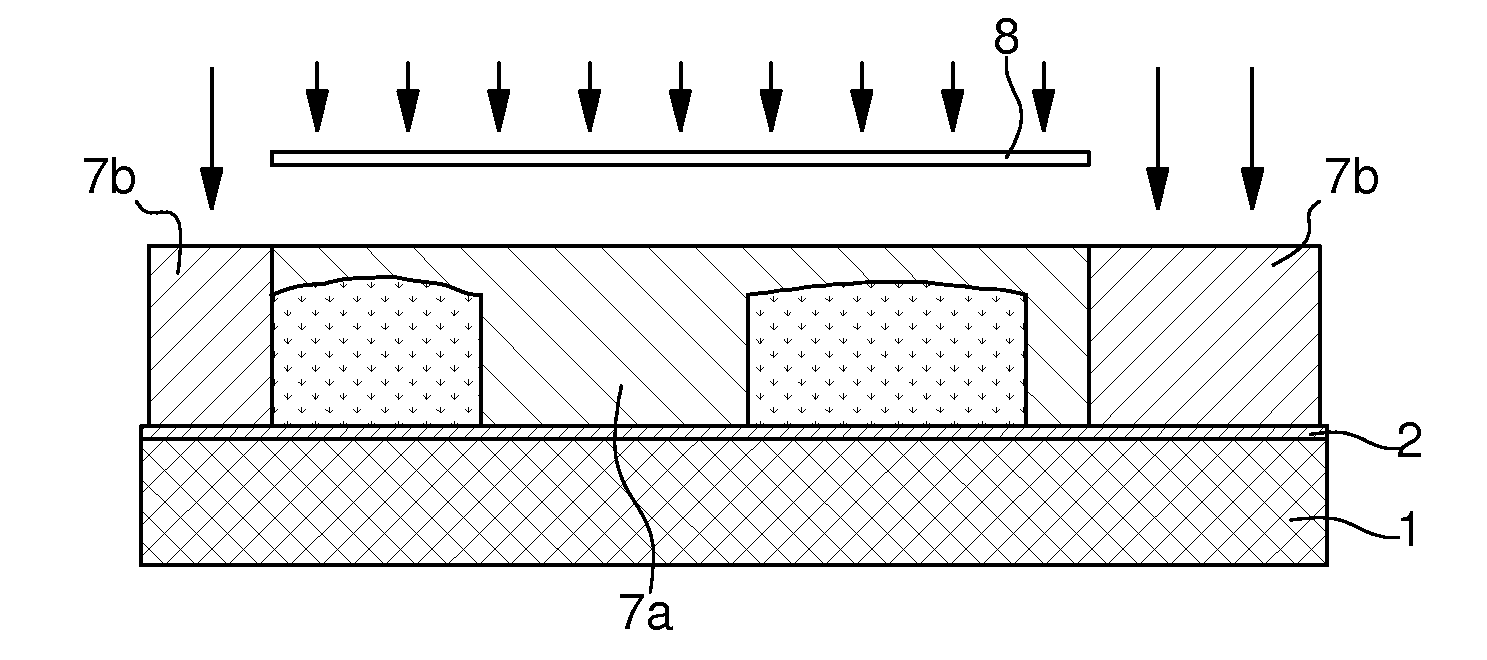
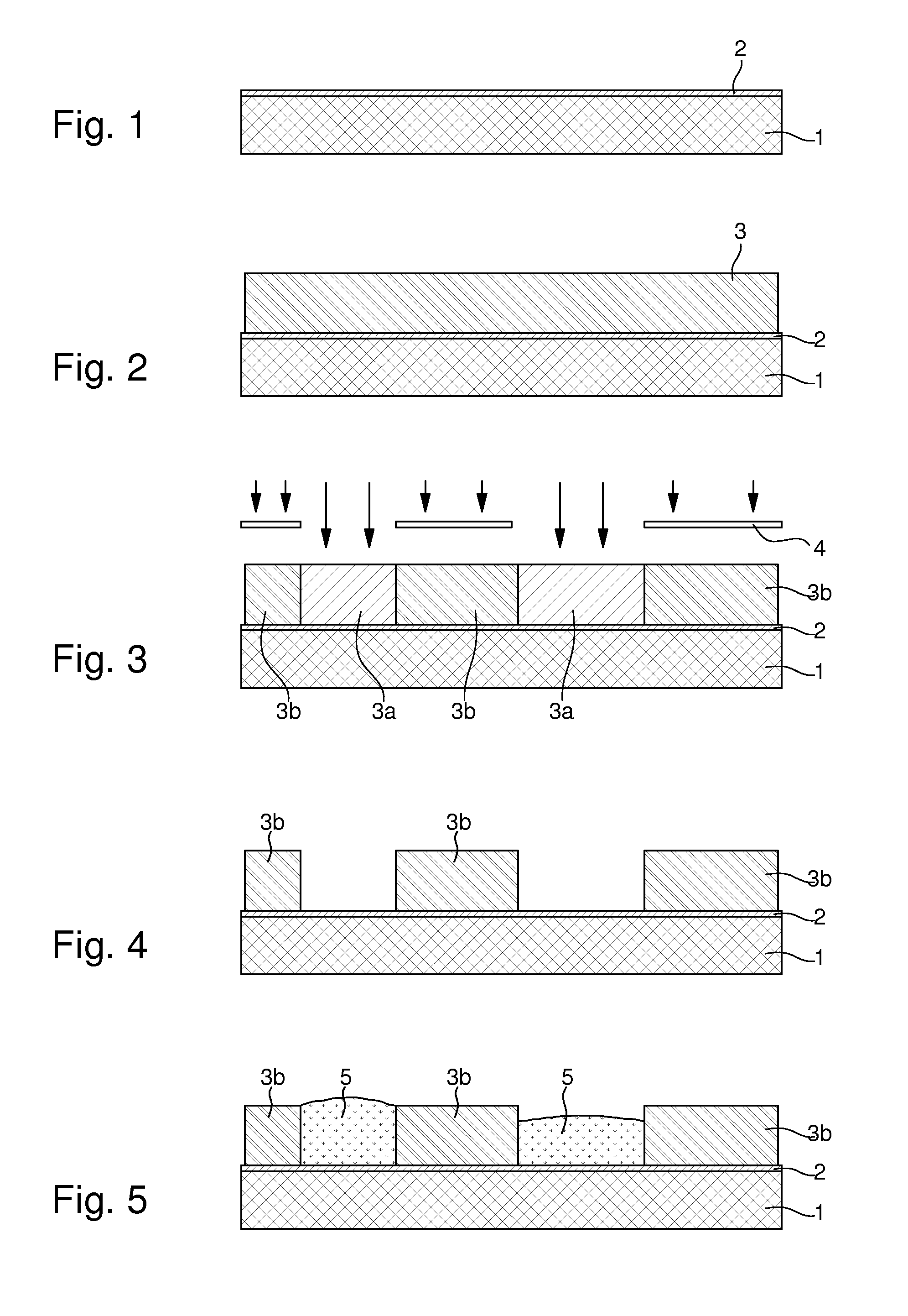
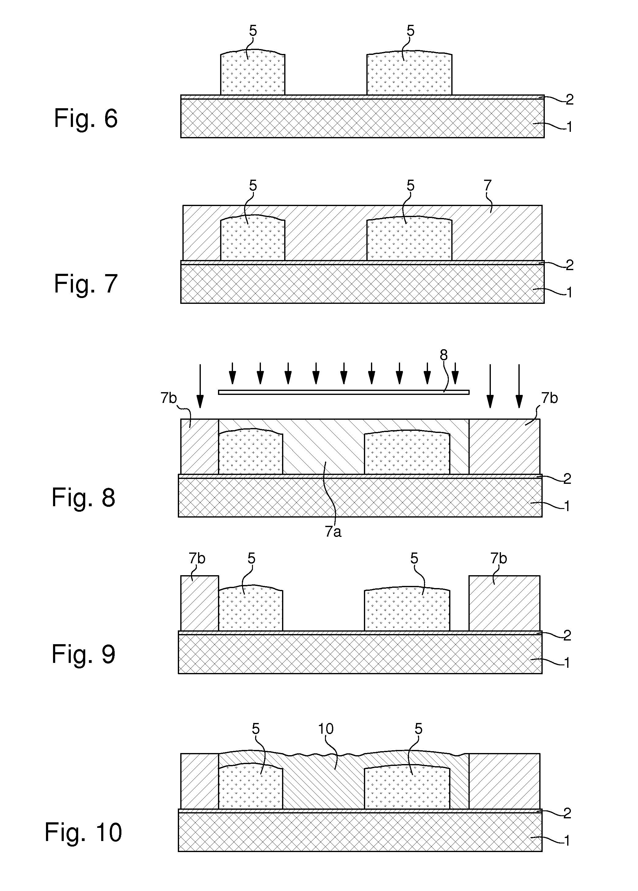
[0039]According to the present invention, the method includes the step of taking a substrate that has a conductive surface. In the particular implementation illustrated in the Figures, substrate 1 is formed by a silicon, glass, or ceramic wafer on which a conductive layer 2 (FIG. 1) has been previously deposited by vacuum plating. This conductive layer 2 is intended to act as a strike layer, i.e. a cathode, during a subsequent galvanic deposition. Typically, strike layer 2 can be formed of a sub-layer of chromium or titanium coated with a gold or copper layer.

[0040]According to a variant that is not shown, to facilitate the subsequent separation of the part from the substrate, a layer with a low degree of cohesion or adherence with the other layers is first of all deposited on the substrate. This layer, called the sacrificial layer, can easily be broken, so as to enable the multi-level metal structure to be separated from the substrate at the end of the method. The sacrificial layer...


PUM

PropertyMeasurementUnit
Electrical conductoraaaaaaaaaa
Microstructureaaaaaaaaaa
Photosensitivityaaaaaaaaaa

Abstract

The method of fabricating metal microstructures includes the following steps:
    • a) taking a substrate (1, 2) that has a conductive strike surface (2);
    • b) to d) forming a first resin mould (3b) by UV photolithography, the apertures in the first resin mould revealing the conductive strike surface (2) of the substrate;
    • e) electroforming the first element (5) by galvanic deposition of a first metal material in the apertures of the first resin mould (3b),
    • f) removing the first mould (3b) around the first element (5) to expose the conductive strike surface (2) of the substrate;
    • g) to i) forming a new resin mould (7b) by UV photolithography, the apertures in the new resin mould revealing the first element (5), and the conductive strike surface (2) of the substrate;
    • j) electroforming the second element (10) by galvanic deposition of a second metal material in the apertures of the new resin mould (7b) to form said metal microstructure;
    • k) separating said metal microstructure from the substrate (1) and from said new mould (7b).

Description

FIELD OF THE INVENTION[0001]The present invention concerns a method of fabricating metal parts by UV photolithography and galvanic deposition. The present invention concerns, more specifically, a method of this type for fabricating parts that comprise at least a first element made of a first metal, inserted into a second element made of a second metal.BACKGROUND OF THE INVENTION[0002]The best known methods of fabricating metal parts by UV photolithography and galvanic deposition are those based on LIGA-UV technology. Originally, LIGA (Lithographie Galvanik Abformung) technology was developed by W. Ehrfled of Karlsruhe Kernforschungszentrum (Germany) in the 1980's. It has proved very advantageous for fabricating high precision metal microstructures.[0003]The principle of the LIGA technique consists in depositing a layer of photosensitive resin on a conductive substrate or a substrate coated with a conductive coating, carrying out X radiation via a synchrotron, through a mask that con...

Claims


Application Information

Patent Timeline
IPC IPC(8): C25D1/00
CPCG03F7/00G04B19/042C25D1/003G04B31/06G04B29/027C25D1/00C25D21/00
Inventor REY-MERMET, GILLES
Owner NIVAROX FAR
Why Eureka
Try Eureka