Manufacturing method of precision metal reflection grating

A technology of metal reflection and manufacturing method, applied in the directions of diffraction grating, optics, optical components, etc., can solve the problems of raising the cost and taking time, and achieve the effect of good consistency, improved effective utilization rate and high precision

Inactive Publication Date: 2020-01-17
INST OF OPTICS & ELECTRONICS - CHINESE ACAD OF SCI +1
View PDF6 Cites 5 Cited by
  • Summary
  • Abstract
  • Description
  • Claims
  • Application Information

AI Technical Summary

Problems solved by technology

Therefore, this technology is still in the stage of laboratory exploration, and it will take time to apply it to industrial production.
At the same time, for devices such as encoders and multi-axis cantilever robots, the tolerance can be controlled at ±1um, and nanometer-level precision gratings are neither necessary nor costly.

Method used


Image

  • Manufacturing method of precision metal reflection grating
  • Manufacturing method of precision metal reflection grating

Examples


Embodiment Construction

[0042] The present invention will be further described below in conjunction with the accompanying drawings and specific embodiments. The following examples are used to illustrate the present invention, but are not intended to limit the scope of the present invention.

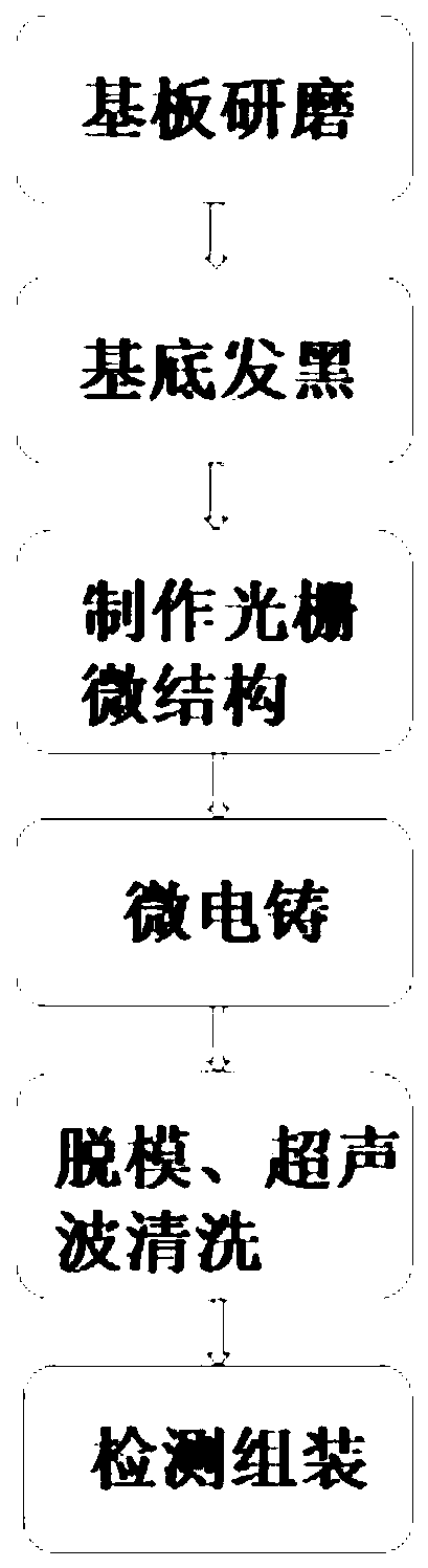
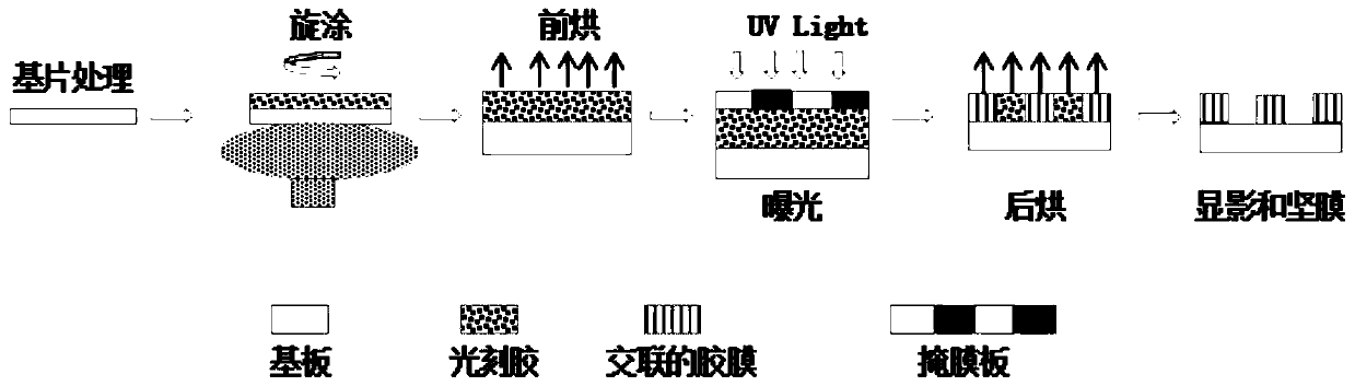
[0043] See figure 1 and figure 2 As shown, the entire process flow of manufacturing a precision metal reflective grating is shown, including the following steps:

[0044] Step 1. Substrate grinding:

[0045] Select a flat metal substrate. The metal substrate can be stainless steel, nickel, copper, aluminum, etc., and the surface of the substrate is cleaned and ground by electrolytic polishing to remove surface impurities, scratches and uneven points. After cleaning and grinding, place it in an oven for baking. It is 150-180°C.

[0046] Step 2, the base is blackened:

[0047] The polished metal substrate is blackened by electroplating, and the blackened metal substrate Ra≤0.02 is produced, and the surface f...


PUM

PropertyMeasurementUnit
thicknessaaaaaaaaaa
thicknessaaaaaaaaaa
thicknessaaaaaaaaaa

Abstract

The invention relates to the field of manufacturing of reflection gratings, and discloses a manufacturing method of a precision metal reflection grating. The manufacturing method comprises the following steps: grinding a substrate; blackening the substrate; manufacturing a grating microstructure; carrying out micro electroforming; carrying out demolding and ultrasonic cleaning; and carrying out detection and assembly. According to the manufacturing method, the technologies such as micro electroforming, UV-LIGA technology, electrolytic polishing and electroplating blackening are fused, so thatthe precision metal reflection grating with good reflection effect, high surface smoothness, high reflection line precision, batch production and relatively low cost can be manufactured.

Description

technical field [0001] The invention relates to the field of manufacturing reflective gratings, in particular to a method for manufacturing precision metal reflective gratings. Background technique [0002] With the rapid development of technology and the continuous expansion of application fields, photoelectric encoders require smaller and smaller line widths and higher precision for gratings. In this case, transmissive gratings based on the principle of Moire fringes have become increasingly Unable to meet the requirements, the reading method of reflective photoelectric signals is gradually becoming the mainstream. This is because: when the reticle line width of the transmissive grating is small (less than 15 μm), the requirements for the parallelism of the light source, shafting end jump, and diameter adjustment are strict, and can only be applied in the laboratory, and the reticle width is lower than At 10um, it is basically impossible to obtain photoelectric signals. ...

Claims


Application Information

Patent Timeline
Patent Type & Authority Applications(China)
IPC IPC(8): G02B5/18
CPCG02B5/1847G02B5/1857G02B5/1861
Inventor 魏晓蓉朱俊涛林树靖张笛王洁
Owner INST OF OPTICS & ELECTRONICS - CHINESE ACAD OF SCI
Why Eureka
Try Eureka