
Systems and methods for detecting data communication over a wireless power link

a data communication and wireless power link technology, applied in the field of wireless power supplies with integrated data communications, can solve the problems of affecting performance, presenting other undesirable issues, and the signal-to-noise ratio inherent in this existing technique is relatively low, and achieves simple and effective systems and methods, a smaller overall input range, and a higher signal-to-noise ratio

Active Publication Date: 2011-08-25
PHILIPS IP VENTURES BV
View PDF51 Cites 40 Cited by
  • Summary
  • Abstract
  • Description
  • Claims
  • Application Information

AI Technical Summary

Benefits of technology

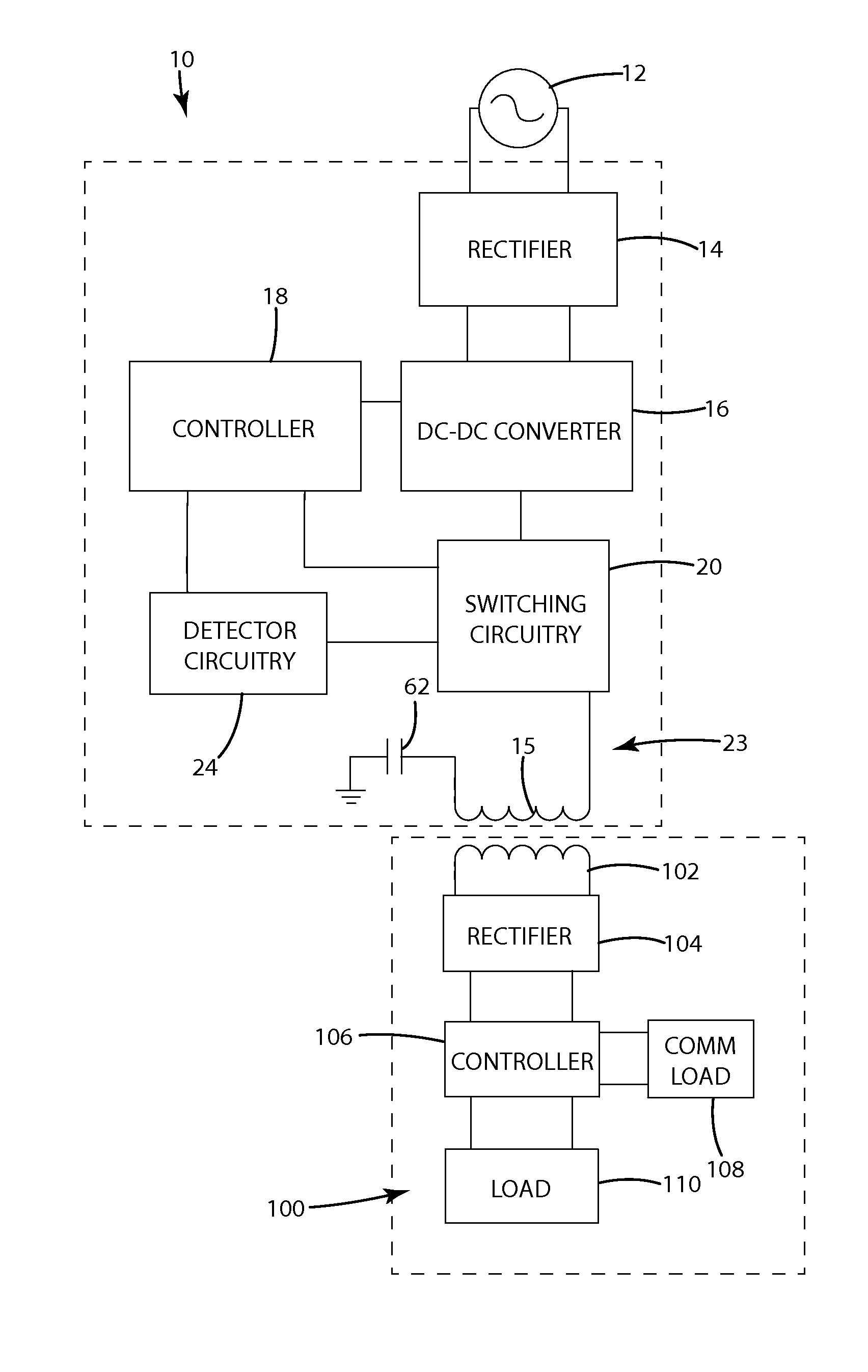
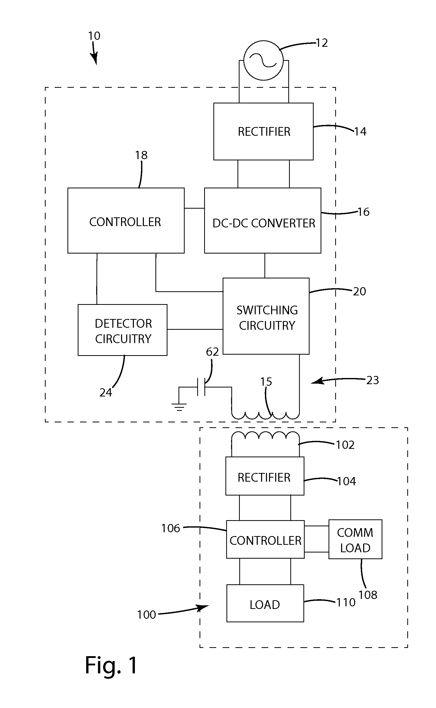
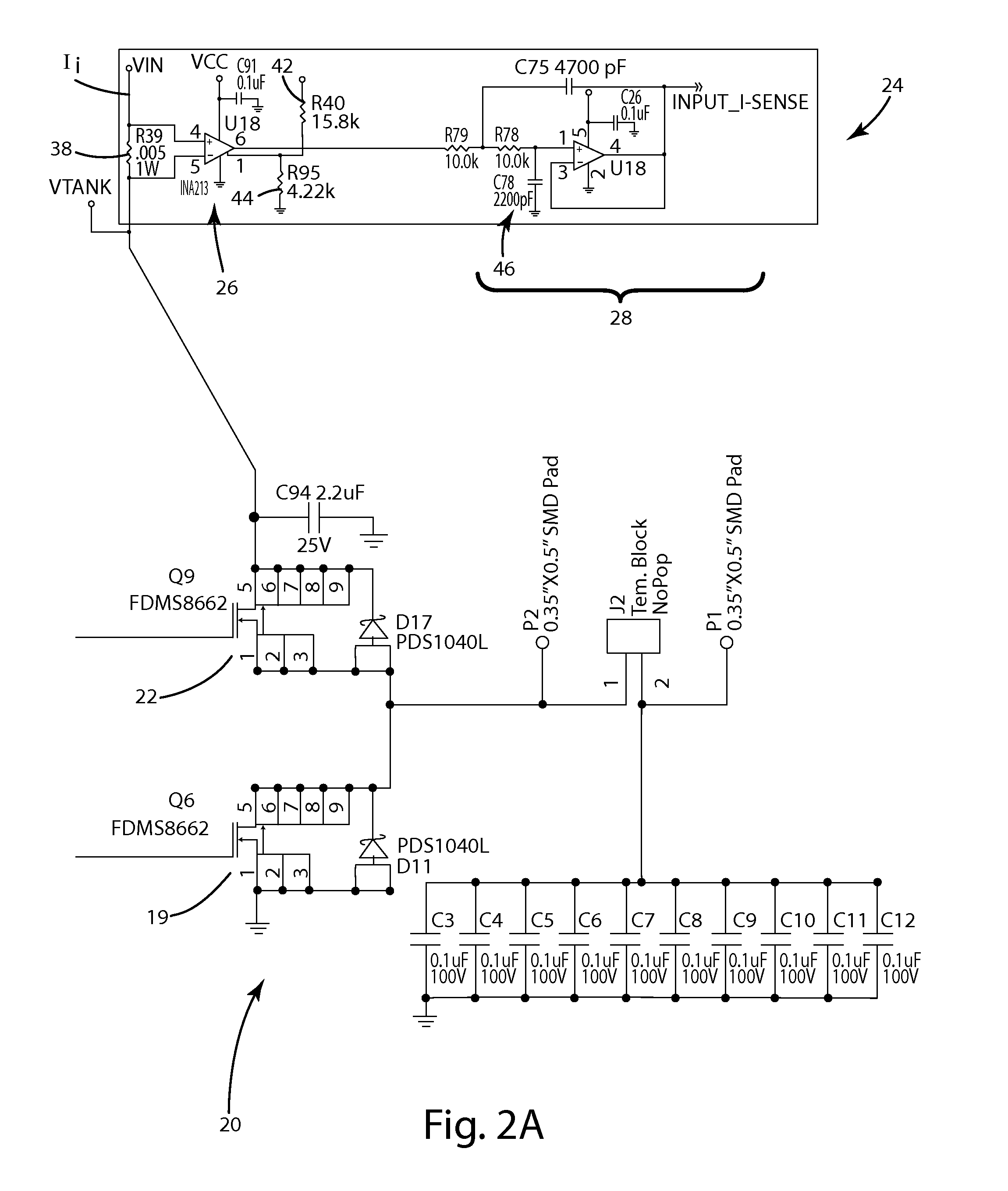
In one embodiment, the present invention provides a method for detecting communications modulated onto a power signal in an inductive wireless power supply. In general, the method includes the steps of: (1) generating a signal that varies with changes in the phase of the current in the tank circuit; (2) filtering the signal with a band-pass filter to remove variations outside the frequency range of the communications, (3) amplifying the filtered signal, (4) filtering the amplified signal to further remove noise and isolate the signal, (5) converting the filtered signal into high and low signals corresponding to the communications, and (6) feeding the converted signals into a controller programmed to interpret the high / low signals as a binary data stream.
The present invention provides simple and effective systems and methods for detecting data communications in the power signal across an inductive load. In the switching circuit input power detection system and method, the input current scales more linearly and more predictably with the current of the secondary-side. This allows the system to be designed for a smaller overall input range and provides a higher signal to noise ratio. The end detection may be simpler and as a result more robust over the operating frequency range. Further, when the imaginary power (primary coil current) remains constant despite a varying load, the real power consumed by the electronic device still changes. By detecting power drawn from the input to primary coil, this change can be seen and translated into digital data. In the phase change detection system and method, the phase change due to a communication load is more linear and presents a higher signal-to-noise ratio than amplitude. When data is present, it causes a phase shift that results in an imbalance between the positive and negative portions of the waveform, which can be detected as a DC level change. The synchronous time slicing allows the positive and negative portions of the current waveform to settle to a constant voltage that may be filtered from the signal when no communications is occurring. Portions of the signal due to changes in the load will self-cancel, allowing the signal derived from the phase change to be clearly detected. As a result, there is less chance of missing communications due to a change in the power from the device.

Problems solved by technology

In a further example, the presence of parasitic metal in range of the wireless power supply may affect performance or present other undesirable issues.
For example, the signal-to-noise ratio inherent in this existing technique may be relatively low in some applications, thereby making it more difficult to discriminate between data and noise.

Method used


Image

  • Systems and methods for detecting data communication over a wireless power link
  • Systems and methods for detecting data communication over a wireless power link
  • Systems and methods for detecting data communication over a wireless power link

Examples


Embodiment Construction

The present invention is directed to systems and methods for detecting on the primary-side of a wireless power supply data communications modulated onto the power signal on the secondary-side. In one aspect, the present invention detects communications in the input power to the switching circuit. In this aspect of the invention, the wireless power supply includes a detector for generating a signal indicative of the current in the input to the switching circuitry, a band-pass filter for filtering the detected signal, an amplifier for amplifying the filtered signal, a filter for filtering the amplified signal and a comparator for converting the final signal into a stream of high and low signals that can be passed to a controller for processing as binary data stream. In a second aspect, the present invention detects communications through changes in the phase relationship between the current and voltage in the primary-side tank circuit. In this second aspect, the wireless power supply ...


PUM


Abstract

A wireless power supply system that detects communications in the input power to the switching circuit. In this aspect of the invention, the wireless power supply includes a detector for generating a signal indicative of the current in the input to the switching circuitry, a band-pass filter for filtering the detected signal, an amplifier for amplifying the filtered signal, a filter for filtering the amplified signal and a comparator for converting the final signal into a stream of high and low signals that can be passed to a controller for processing as binary data stream. In a second aspect, the wireless power supply system includes a detector for generating a signal that varies in dependence on changes in the phase relationship between the current and the voltage in the primary-side tank circuit, a band-pass filter for filtering the signal, an amplifier for amplifying the filtered signal, a filter for filtering the amplified signal and a comparator for converting the final signal into a stream of high and low signals that can be passed to a controller for processing as binary data stream.

Description

BACKGROUND OF THE INVENTIONThe present invention relates to wireless power supplies, and more particularly to wireless power supplies with integrated data communications.There is an increased effort in the market to develop wireless power supply systems capable of charging and / or powering a wide variety of electronic devices. Wireless power supply systems allow power to be delivered to an electronic device without the need for direct-wired connections. This eliminates a variety of problems associated with direct electrical connections, such as the mess and clutter associated with cords as well as the inconvenience associated with repeatedly plugging in and disconnecting charging cords from portable electronic devices.Many conventional wireless power supply systems rely on inductive power transfer (i.e. the transfer of power using electromagnetic fields) to convey electrical power without wires. A typical inductive power transfer system includes an inductive power supply that uses a ...

Claims


Application Information

Patent Timeline
Patent Type & Authority Applications(United States)
IPC IPC(8): H02J3/02
CPCH02J5/005H04B5/0025H04B5/0093H04B5/0037H04B5/0031H02J50/80H02J50/12H04B5/70H04B5/72H04B5/79H04B5/266H02J7/025H04B5/24H02J50/90
Inventor NORCONK, MATTHEW J.MOLLEMA, SCOTT A.BAARMAN, DAVID W.SCHWANNECKE, JOSHUA K.LIFF, DALE R.ZEIK, ANDREW C.BLAHA, MARK A.GRUICH, ROBERT D.AMISTADI, JASON L.
Owner PHILIPS IP VENTURES BV
Learn More