Method and apparatus for applying material to a surface of an anode of an x-ray source, anode and x-ray source

a technology of x-ray source and surface, applied in the direction of x-ray tube target treatment, x-ray tube target and convertor, etc., can solve the problems of damage, x-ray beam may start flickering more and more, damage at the surface of the anode, etc., to avoid contamination and reduce the number of necessary light sources

Inactive Publication Date: 2011-09-01
KONINKLIJKE PHILIPS ELECTRONICS NV
View PDF3 Cites 8 Cited by
  • Summary
  • Abstract
  • Description
  • Claims
  • Application Information

AI Technical Summary

Benefits of technology

[0031]By optically detecting the damaged surface regions, recesses or grooves in the anode's surface can be reliably and precisely detected without mechanically contacting the surface thereby avoiding any contamination.
[0032]Furthermore, according to an embo

Problems solved by technology

For example, after a certain period of time, the focal track of the electron beam on the surface of the anode of the X-ray tube may have been loaded with thermal and/or mechanical stress such that damages at the surface of the anode may occur.
Such damages can be visible changes like e.g. cracks within the focal track.
Due to such damages, the X-ray beam may start flickering more and more and hence the intensity of the X-ray beam may vary in an unpredictable way.
In particula

Method used


Image

  • Method and apparatus for applying material to a surface of an anode of an x-ray source, anode and x-ray source
  • Method and apparatus for applying material to a surface of an anode of an x-ray source, anode and x-ray source
  • Method and apparatus for applying material to a surface of an anode of an x-ray source, anode and x-ray source

Examples


Embodiment Construction

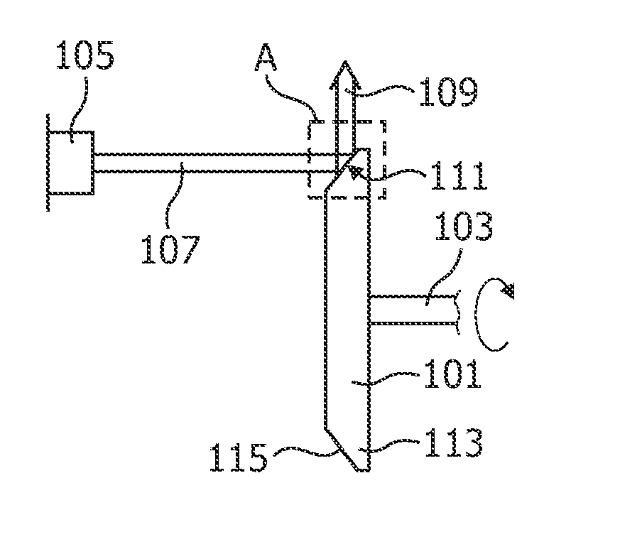
[0063]FIG. 1 shows an X-ray tube arrangement including disk-shaped anode 101 and an electron source 105. The anode 101 is disk-shaped and comprises a heavy metal such as tungsten, rhenium or molybdenum. At its circumferential border 113 the anode 101 comprises a slanted surface which acts as an X-ray emitting surface 115 for emitting an X-ray beam 109 when irradiated by an electron beam 107 coming from the electron source 105. At the focal track 111 where the electron beam 107 impacts onto the X-ray emitting surface 115, cracks or recesses may occur after continuous operation of the X-ray tube.

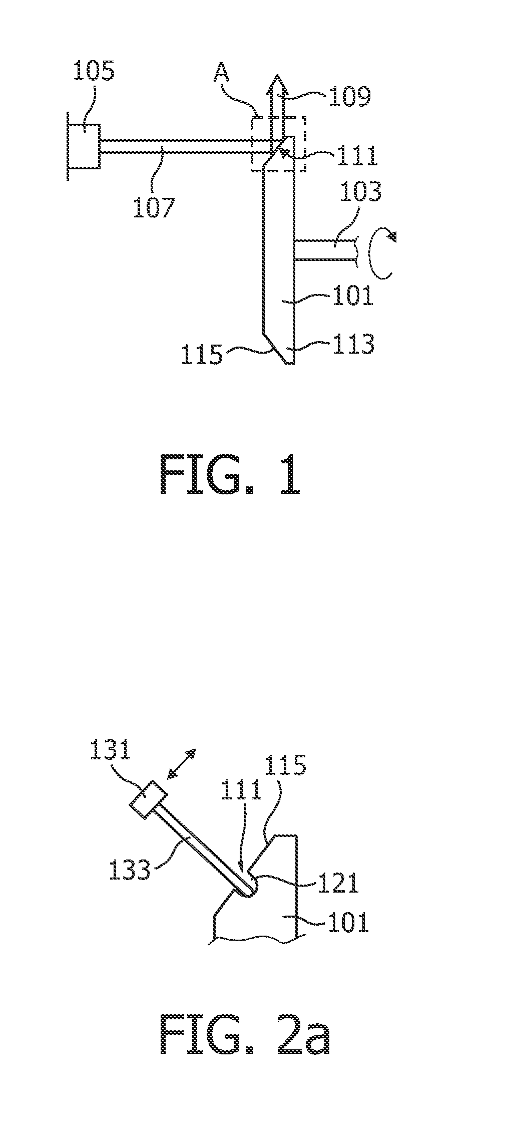
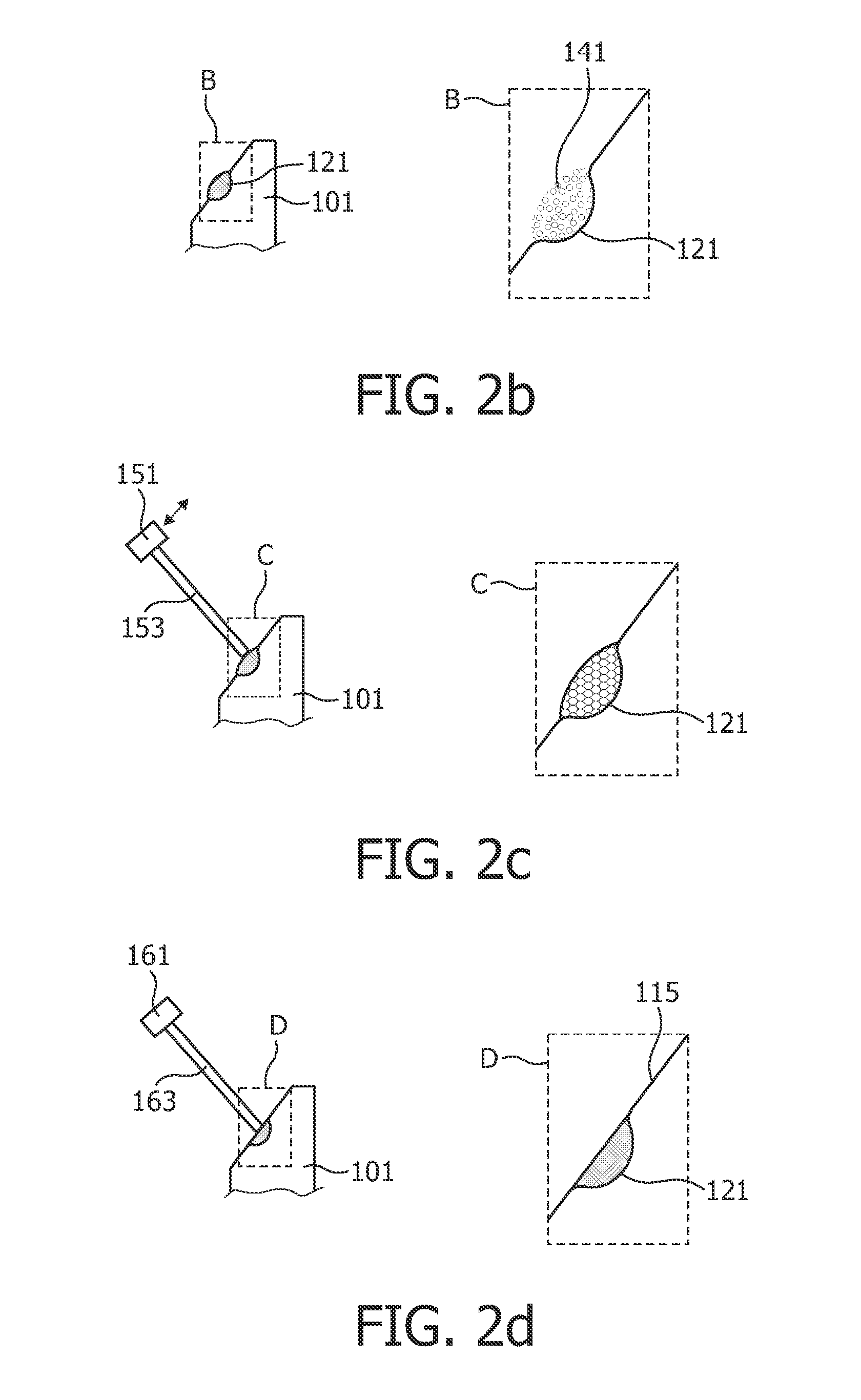
[0064]FIGS. 2a to 2d show the region A in the neighbourhood of the focal track 111 as indicated in FIG. 1 during different process steps of an embodiment of the method according to the present invention.

[0065]As shown in FIG. 2a, a recess 121 formed on the focal track 111 may be detected and its depth may be measured using a laser beam 133 coming from a first laser 131. As indicated by the arr...


PUM

PropertyMeasurementUnit
Poweraaaaaaaaaa
Structureaaaaaaaaaa
Sizeaaaaaaaaaa

Abstract

A method and an apparatus for locally applying material to the surface of an anode of an X-ray source as well as a corresponding anode is presented. Anode material such as a repair material for filling a recess (121) in an X-ray emitting surface (115) is applied to the X-ray emitting surface of an anode (101). The location where such material is to be applied may be detected using a laser beam (133). The applied repair material including particles (41) of anode material such as tungsten, rhenium or molybdenum, is subsequently locally sintered using a high-energy laser beam (151). The sintered material may then be melted using a high-energy electron beam (163). Using such method, a damaged surface of an anode may be locally repaired. Alternatively, structures of different anode materials or of protrusions having different levels can be provided on the X-ray emitting surface (115) in order to selectively manipulate the X-ray emitting characteristics of the anode (101).

Description

FIELD OF THE INVENTION[0001]The present invention relates to a method and an apparatus for applying material to a surface of an anode of an X-ray source. Particularly, the present invention relates to a method and an apparatus for repairing an anode of an X-ray source or for providing a surface structure at a surface of an anode of an X-ray source. Furthermore, the present invention relates to an anode having specific electron optical properties and to an X-ray source comprising such anode.TECHNICAL BACKGROUND[0002]X-ray sources are used in a wide variety of applications such as medical applications where for example two-dimensional or three-dimensional images of a patient to be examined can be obtained using X-ray projection and corresponding X-ray detectors. In the X-ray source, a beam of accelerated electrons is directed to a surface of an anode. When impacting on the anode, the electrons are decelerated while emitting X-rays.[0003]The structure of an X-ray emitting surface of an...

Claims


Application Information

Patent Timeline
IPC IPC(8): H01J35/08C23C14/30C23C14/14B05C9/12
CPCH01J35/08H01J2235/085H01J2235/083H01J35/101
Inventor DORSCHEID, RALFVOGTMEIER, GEREONPIETIG, RAINER
Owner KONINKLIJKE PHILIPS ELECTRONICS NV
Why Eureka
Try Eureka