
Device and method for conversion of biomass to biofuel

a biofuel and biomass technology, applied in the direction of fuels, waste based fuels, energy inputs, etc., to achieve the effects of reducing transportation costs, high performance, and high energy density

Inactive Publication Date: 2011-09-08
RENEWABLE FUEL TECH
View PDF8 Cites 31 Cited by
  • Summary
  • Abstract
  • Description
  • Claims
  • Application Information

AI Technical Summary

Benefits of technology

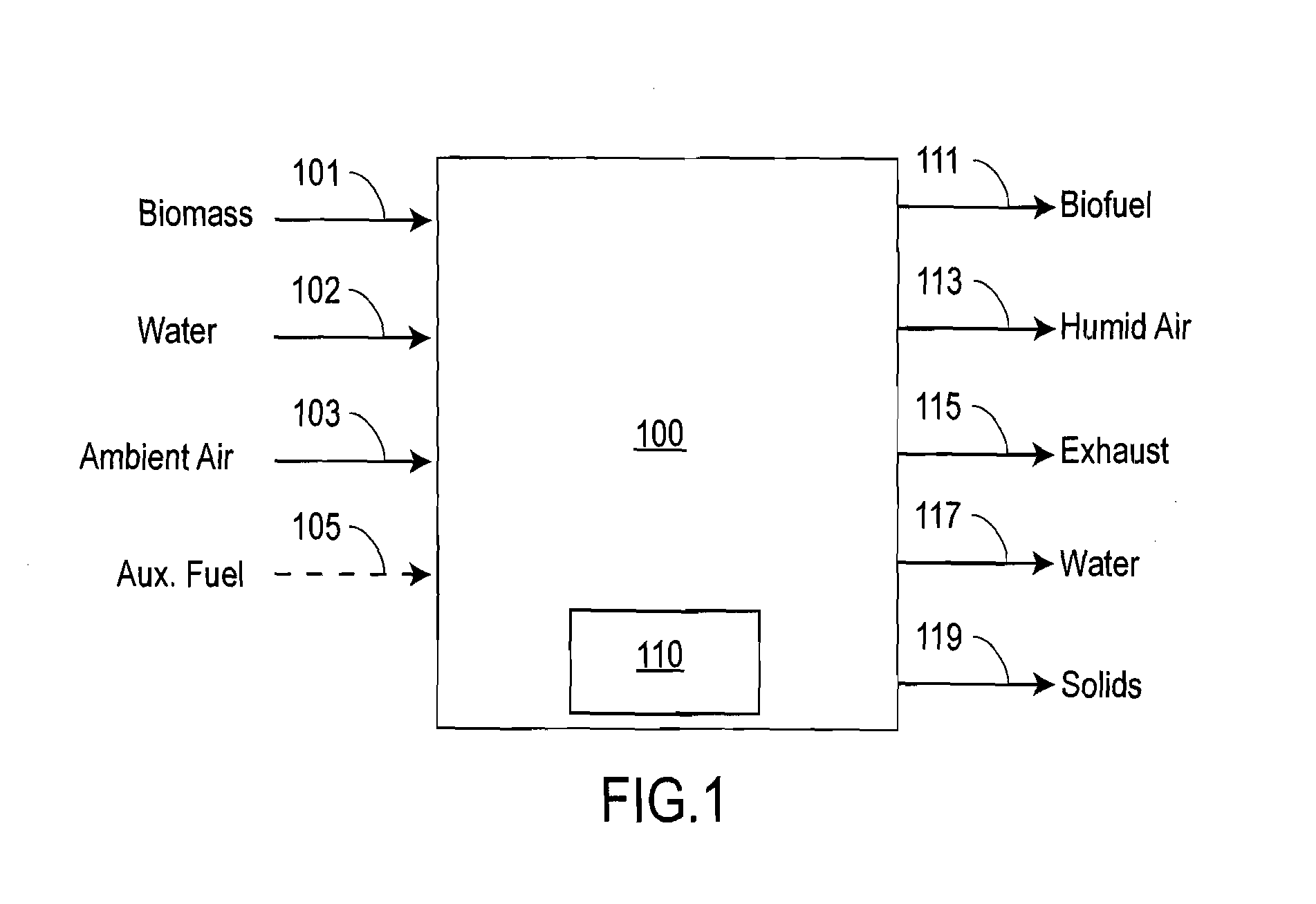
[0013]Embodiments presented herein overcome the disadvantages of prior art by remotely converting biomass to a biofuel. For example, one embodiment is an apparatus that may be placed near a source of biomass and processes the biomass into a biofuel, which is then transported to market. Such apparatus has several advantages. First, the biomass can be converted to a biofuel that is more generally usable than the raw biomass. Second, biofuels have a higher energy density than biomass, thus reducing the transportation cost per energy stored within the fuel. Third, previously uneconomic biomass resources, particularly remote resources, can be economically brought to market.
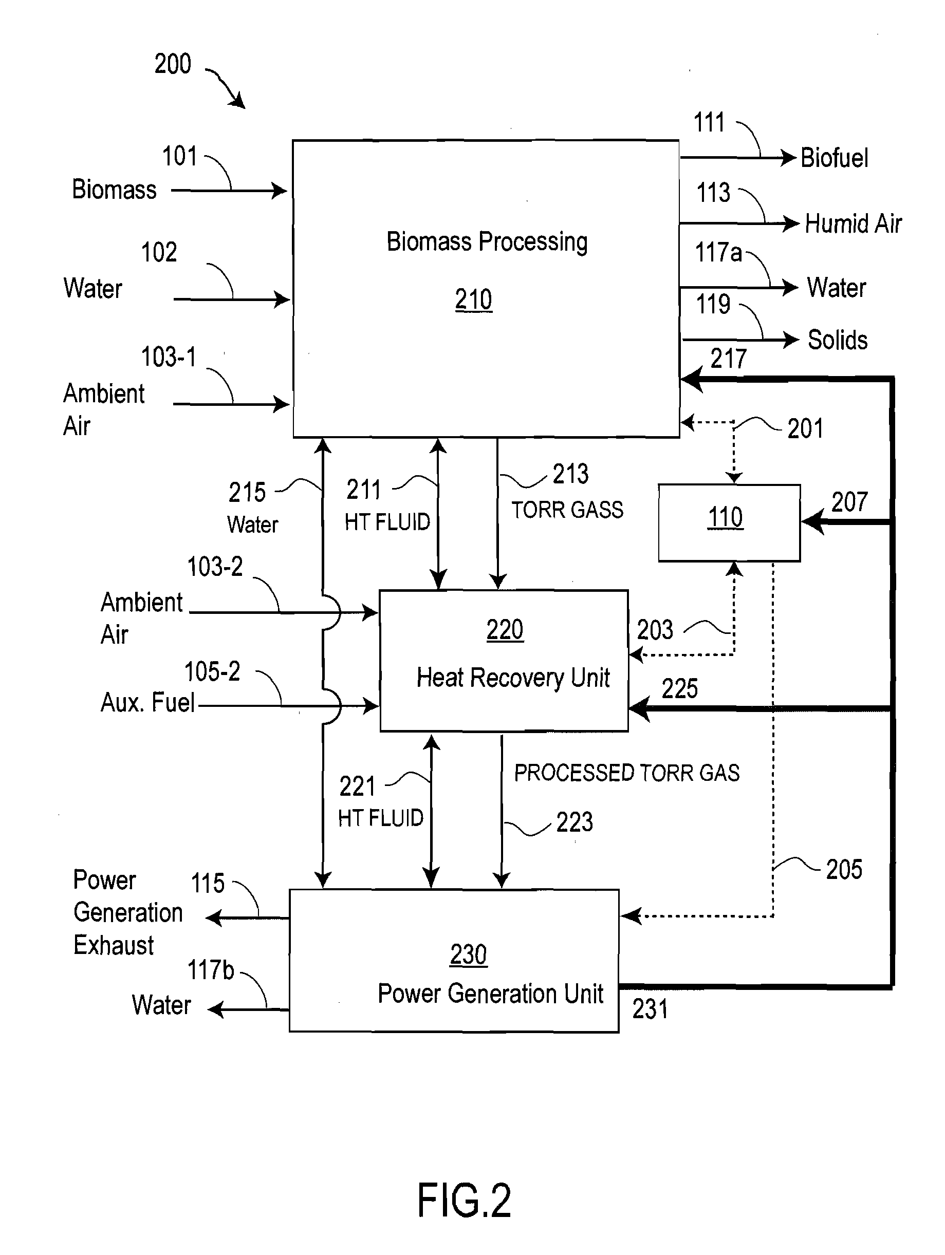
[0014]In certain embodiments, the apparatus and method converts carbonaceous materials, such as biomass which may be remotely located, into a high performance solid fuel for use in industrial combustion processes. The apparatus and method may provide a continuous process which can be completely powered by the energy contained in the biomass. Thus the heat, mechanical power and electrical power may be provided from the energy in the biomass. The apparatus is thus free to operate in remote locations, where no power or auxiliary fuel sources are available. In certain embodiments, utility services and / or auxiliary fuel may be available and may be utilized to simplify the apparatus.

Problems solved by technology

Third, previously uneconomic biomass resources, particularly remote resources, can be economically brought to market.

Method used


Image

  • Device and method for conversion of biomass to biofuel
  • Device and method for conversion of biomass to biofuel
  • Device and method for conversion of biomass to biofuel

Examples


example

[0129]FIG. 7 is a schematic of a proof-of-principle heat exchanger 900 constructed to verify the ability to torrefy biomass. Biomass is provided to upper load lock 901 and transferred through pinch valve to lower load lock 903 and to an output load lock 908. Heat exchanger 900 includes a single auger 902 having an auger motor drive 904 that moves biomass through a vapor condensing zone 905, a vapor condensing zone 907, and a fluid heating zone 909. Heat exchanger 900 also includes a first boiler 910 to maintain a first heat transfer fluid level 911, a second boiler 920 to maintain a second heat transfer fluid level 921. Torr gases could be sampled at ports 931 and 933.

[0130]Vapor condensing zone 905 corresponds to biomass dryer 310, vapor condensing zone 907 corresponds to biomass torrefier 320, and fluid heating zone 909 corresponds to cooling biomass cooler 330.

[0131]The auger had a 4″ diameter auger, was 8 feet (2.5 m) long and had a screw pitch of 4 inches (0.1 m). The auger is ...


PUM

PropertyMeasurementUnit
temperatureaaaaaaaaaa
densityaaaaaaaaaa
densityaaaaaaaaaa

Abstract

Embodiments presented herein describe an apparatus and method to convert carbonaceous materials, particularly biomass and those biomass resources which are remotely located, into a high performance solid fuel. This method, and the apparatus described as the means to accomplish this method, provides a continuous process which can be completely powered by the energy contained in the biomass. The heat, mechanical power and electrical power are provided from the energy in the biomass, through the methods described. In this way, the apparatus is free to operate in remote locations, where no power or auxiliary fuel sources are available.

Description

CROSS-REFERENCE TO RELATED APPLICATIONS[0001]This application claims the benefit of U.S. Provisional Application No. 61 / 311,696 filed Mar. 8, 2010. The entire contents of the above-listed provisional application are hereby incorporated by reference herein and made part of this specification.BACKGROUND OF THE INVENTION[0002]1. Field of the Invention[0003]The present invention generally relates to the production of fuels from biomass, and more particularly to a self-contained method and system for generating biofuels from biomass.[0004]2. Discussion of the Background[0005]The use of solid fuels is the world's largest energy market. In the United States, solid fuels are used primarily for generating electric power and in metallurgic and cement manufacturing processes. This market is dominated by non-renewable resources, principally coal, and to a lesser extent petroleum coke. Biomass sources, which are generally considered to be renewable, form less than 5% of the U.S. Market.[0006]The...

Claims


Application Information

Patent Timeline
Patent Type & Authority Applications(United States)
IPC IPC(8): C10L5/44B01J19/00
CPCY02E50/32C10L5/447C10B53/02C10L9/083Y02E50/10Y02E50/14Y02E50/15C10L2290/10C10L2290/06C10L2290/08C10L2290/28C10L2290/567C10L2290/52Y02E50/30C10B47/44Y02P20/129
Inventor WECHSLER, MARKSHULENBERGER, ARTHUR M.
Owner RENEWABLE FUEL TECH
Features
  • Generate Ideas
  • Intellectual Property
  • Life Sciences
  • Materials
  • Tech Scout
  • Unparalleled Data Quality
  • Higher Quality Content
  • 60% Fewer Hallucinations
Learn More