
Cold-Start Fuel Control System

a fuel control system and cold-start technology, applied in the direction of liquid fuel feeders, electric control, machines/engines, etc., can solve the problems of reduced maximum, reduced transient response from the lower system, engine will not be able to start, etc., to achieve the effect of improving cold-start operation

Inactive Publication Date: 2011-09-08
WOODWARD GOVERNOR CO
View PDF26 Cites 23 Cited by
  • Summary
  • Abstract
  • Description
  • Claims
  • Application Information

AI Technical Summary

Benefits of technology

The present invention provides a new and improved liquefied petroleum gas (LPG) fuel control system for controlling fuel supplied to an engine from an LPG tank. The system addresses issues such as failure to vaporize LPG during cold-start operations and limited fuel blend options. The system includes a cold-start fuel control valve that throttles the supply of liquid LPG to the engine during cold-start operations, allowing the LPG to vaporize and avoid flooding the engine. The system also compensates for changes in fuel blend settings and optimizes system performance by automatically adjusting fuel pressure settings. The system includes a controller that senses various characteristics of the LPG and operates the cold-start fuel control valve accordingly. The system can also adapt to changing conditions and includes a heat exchanger to perform the function of a pressure regulator during normal engine operation. The method includes steps of sampling the temperature and pressure of the LPG, supplying a discrete amount of LPG to an injector arrangement, and monitoring the pressure of the LPG.

Problems solved by technology

As such, liquid fuel will be introduced to the injectors and the engine will not be able to start due to an extremely fuel rich fuel-to-air mixture within the combustion chamber.
This is generally a problem when high amounts of butane are present in the fuel, the ambient temperature is cold, the fuel is cold, the engine is cold, and / or a high-pressure injection system is used.
As such, this becomes a particular problem when vehicles are stored outside during cold winter months.
However, if a system uses this manual adjustment method, doing so may require other changes to the system hardware to increase fuel flow (i.e. adding additional injectors to the system, larger injectors, other additional hardware) to avoid adverse affects to system performance such as reduced maximum engine power due to restricted fuel flow from reduced pressure, reduced transient response from lower system pressure, poorer fuel control, loss of the ability to seal the system, etc.

Method used


Image

  • Cold-Start Fuel Control System
  • Cold-Start Fuel Control System
  • Cold-Start Fuel Control System

Examples


Embodiment Construction

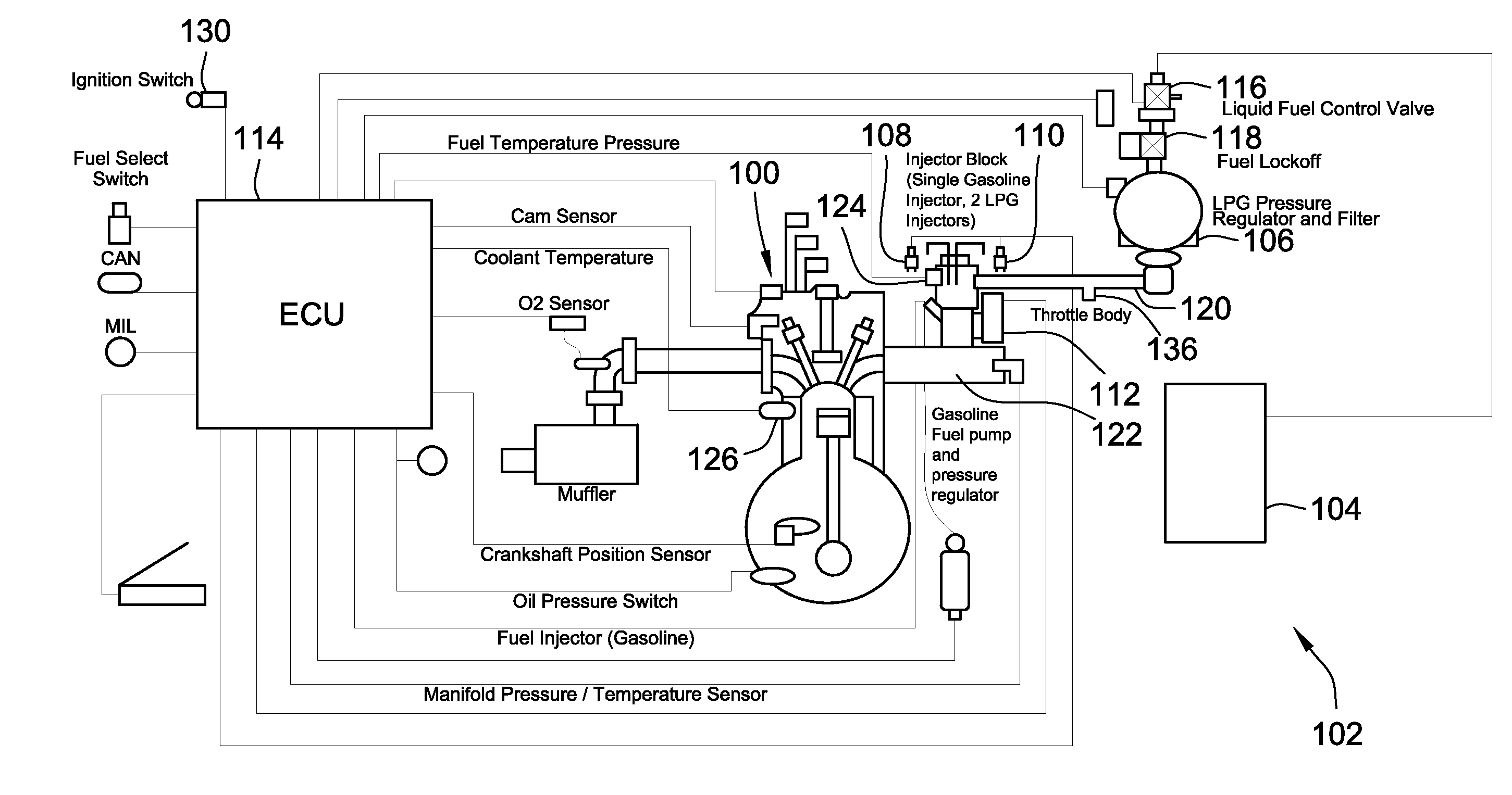
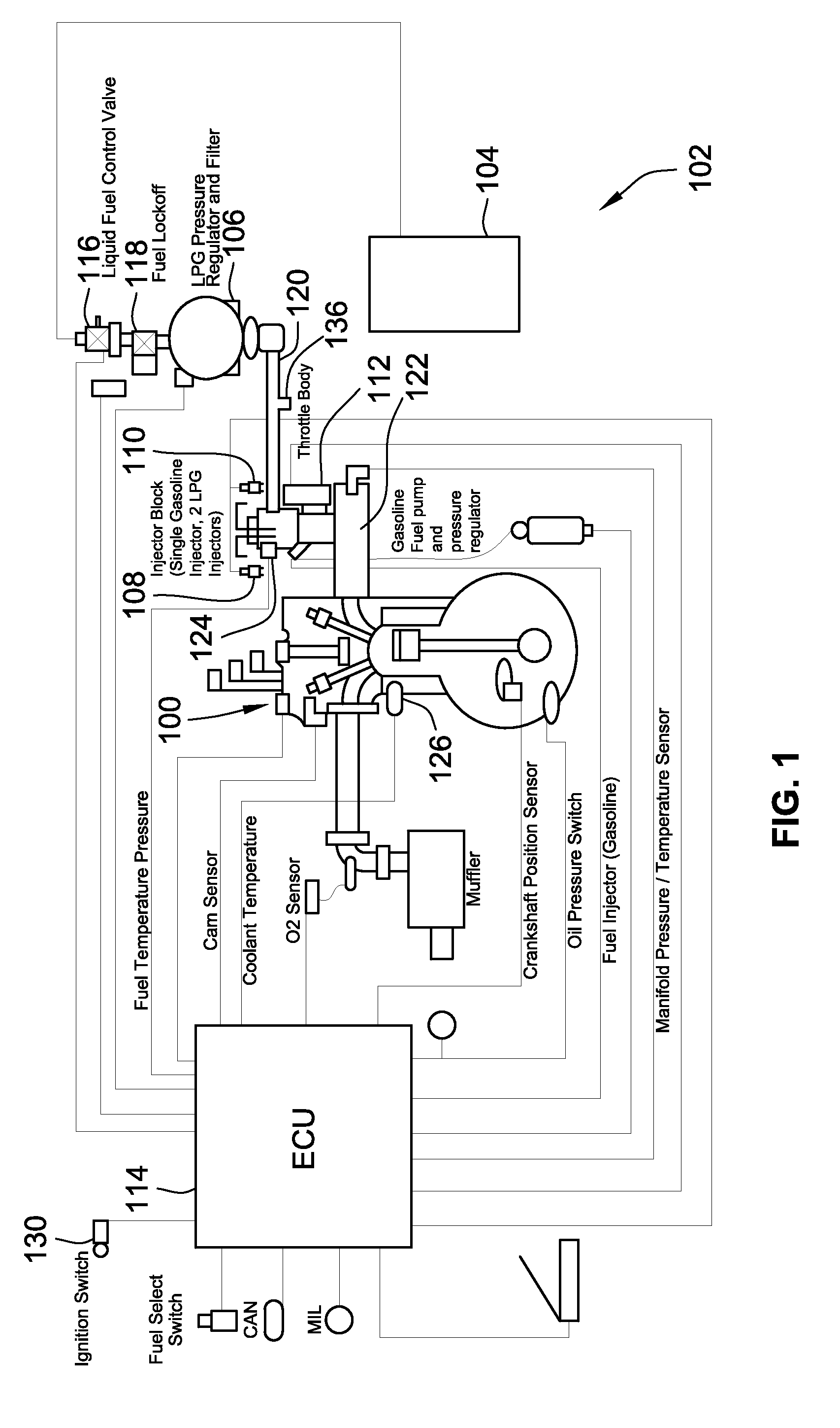
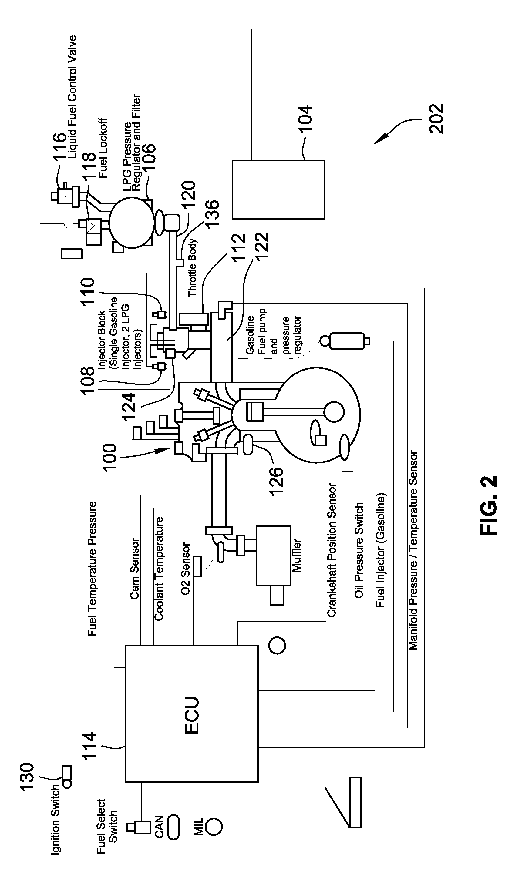
FIG. 1 is a schematic representation of an exemplary embodiment of a engine 100 having a fuel control system 102 according to an embodiment of the present invention. The fuel control system 102 controls the supply of fuel to the engine 100 from a storage tank 104 (also referred to as a bottle) to maximize engine performance. This is accomplished by providing optimum fuel-to-air ratios based on various engine parameters such as fuel temperature, fuel pressure, engine temperature, crankshaft position, intake manifold pressure, etc. In the illustrated embodiment, the primary fuel supplied to the engine 100 is liquefied petroleum gas (LPG) stored in tank 104.

The present system is configured to overcome the long standing problems associated with cold-starting engines using LPG. More particularly, the system avoids the need to adjust the nominal set point pressure of the LPG pressure regulator 106 to a lower value during cold-starting to promote vaporization of the LPG prior to the LPG be...


PUM


Abstract

A fuel control system for controlling the supply of liquefied petroleum gas (LPG) to injectors of a fuel supply system during a cold start is provided. The fuel control system includes a LPG pressure regulator and a cold-start fuel control valve for throttling fuel to the injectors when the pressure of the LPG is below a nominal set point pressure of the pressure regulator. The cold-start fuel control valve may be in parallel or series with a fuel lock-off valve. The system is configured to supply limited discrete amounts of LPG to the injectors when the pressure of the LPG is below the nominal set point pressure to allow the LPG to vaporize prior to being injected, by the injector, into an engine. Operation of the cold-start fuel control valve during non-cold starts and normal operation are also provided.

Description

FIELD OF THE INVENTIONThis invention generally relates to fuel control systems and particularly fuel control systems configured to improve cold starting of combustion engines and more particularly combustion engines that use liquefied petroleum gas (LPG).BACKGROUND OF THE INVENTIONLiquefied petroleum gas (LPG) used on mobile applications is often stored in a saturated liquid state in a tank or bottle and the fuel is fed to the fuel control system as a liquid. The pressure of the liquid being fed to the system is directly dependent on the temperature of the fuel in the tank and the composition of the fuel.If the tank pressure is lower than the systems nominal set point (e.g. the pressure at which it is to be supplied to the fuel injectors during normal operation), the pressure regulator upstream of the fuel injectors will not be active. This is because the pressure will already be lower than the nominal set point to which the pressure regulator is configured to drop the pressure of t...

Claims


Application Information

Patent Timeline
Patent Type & Authority Applications(United States)
IPC IPC(8): F02M37/04
CPCY02T10/36F02M37/04Y02T10/32F02D41/0027F02D41/064F02M21/0212F02M21/023F02D2200/0611F02D2200/0606F02D2200/0602Y02T10/30F02M21/0239F02M21/06F02D19/027F02D19/022F02M21/0287F02M21/0215F02M21/02F02D19/02F02D41/06F02M37/00
Inventor BARTA, JASON C.BLOEMEN, MICHAEL W.BRANDL, STEPHAN M.
Owner WOODWARD GOVERNOR CO
Learn More