Pseudo-CW Quantum Cascade Laser System

a quantum cascade laser and quantum cascade technology, applied in the field of laser systems, can solve the problems of limiting the usefulness of qc lasers in these applications, low efficiency, and only 1% efficiency of qc lasers, and achieves high overall wall-plug efficiency, lower duty cycle, and high efficiency.

Inactive Publication Date: 2011-09-08
GK TECHCOM
View PDF6 Cites 13 Cited by
  • Summary
  • Abstract
  • Description
  • Claims
  • Application Information

AI Technical Summary

Benefits of technology

[0011]The duty cycle of each individual laser can be tailored to provide the desired output for a specific application. For example, in applications where a higher output power is required, one or more of the individual lasers can be configured to have a higher duty cycle (e.g., 75, 80, even 99%), at the expense of wall-plug efficiency. Alternatively, each laser may be controlled to operate at its individual peak walk-plug efficiency (...

Problems solved by technology

However, QC lasers exhibit an efficiency on the order of only 1% (when operated in CW mode near room temperature).
Efficiency is an important parameter in applications where the overall power budget is tight, and the low efficiency of QC lasers in this regime limit their usefulness in these applications.
Additionally, the performance of conventional QC lasers is fundamentally limited by their need to maintain operating temperatures within a rather st...

Method used


Image

  • Pseudo-CW Quantum Cascade Laser System
  • Pseudo-CW Quantum Cascade Laser System
  • Pseudo-CW Quantum Cascade Laser System

Examples


Embodiment Construction

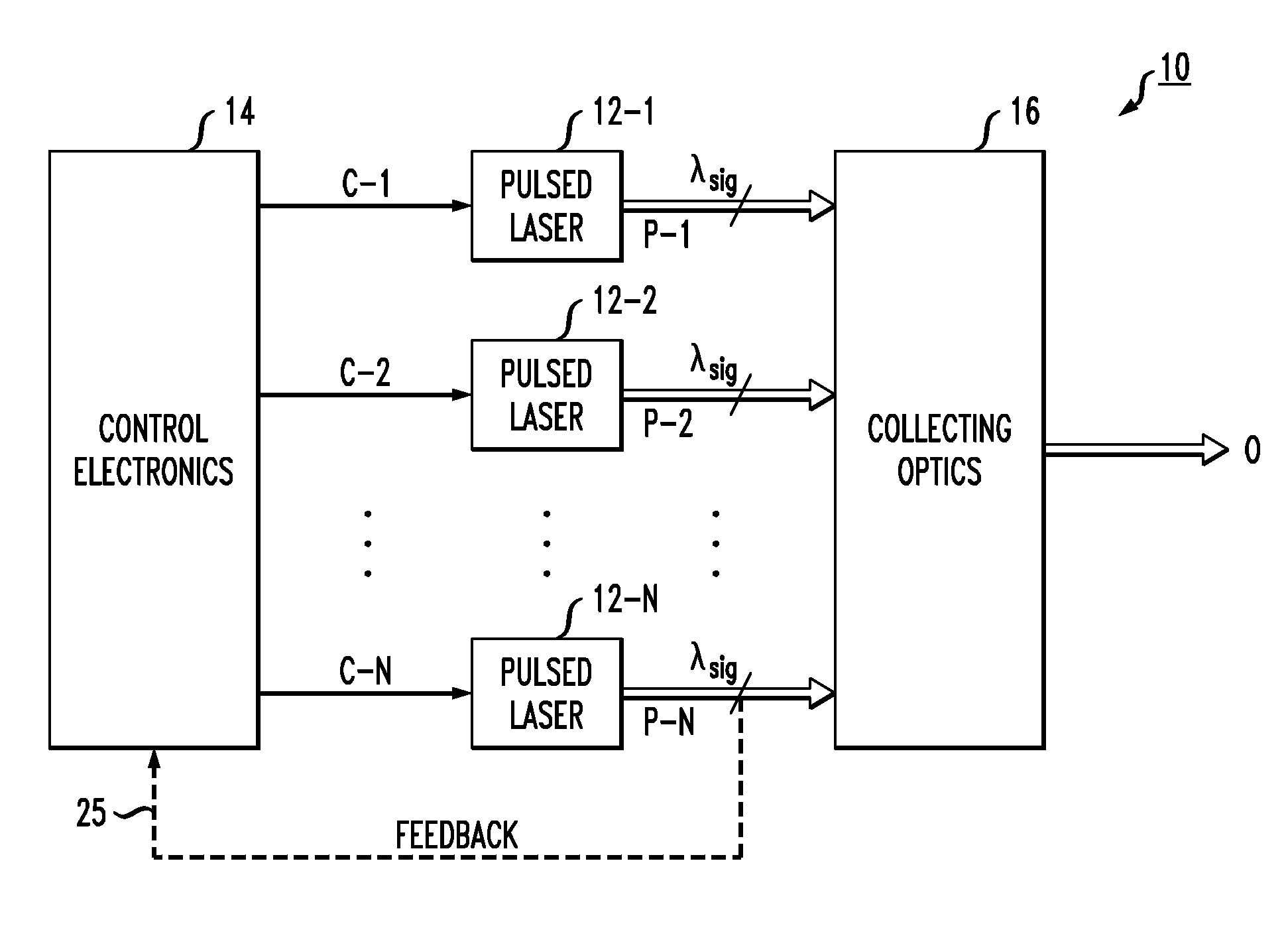
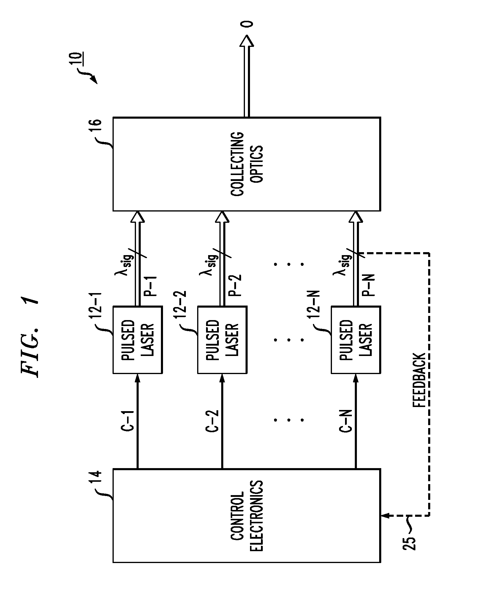
[0024]FIG. 1 is a simplified block diagram of an exemplary laser system 10 formed in accordance with the present invention. As shown, system 10 comprises a plurality of N lasers 12, where N 2. As mentioned above, each laser 12-i may be separately packaged, or groups of the lasers may each be mounted on a separate substrate, or the entire plurality of lasers may be formed as a monolithic structure on a single substrate. Importantly, each laser operates at essentially the same wavelength λsig, so that the output pulses from each separate laser may be combined to form the desired pseudo-CW output signal. As mentioned above, the operating wavelength of the plurality of lasers 12 may also be tunable, providing a pseudo-CW output signal at any desired wavelength over, for example, the mid-IR wavelength range.

[0025]Also shown in FIG. 1 is control electronics 14, which is used to control the operation of each of the separate lasers forming the plurality of N lasers 12. A separate control si...


PUM


Abstract

A laser system is proposed that is configured to provide a pseudo-CW signal at room temperature. The system utilizes an array of pulsed lasers that are controlled (in terms of turning “on” and “off”) to provide, in combination, a quasi-CW output signal. The activation of each individual laser is controlled to turn “on” and “off” in a predefined sequence, where at least one laser is “on” at any given point in time. Thus, by combining the outputs from the plurality of pulsed lasers onto a single output signal path, the resultant output signal from the system will be a pseudo-CW signal (the amount of “ripple” present in the signal controlled by factors such as the number of individual lasers in the plurality of lasers, the duty cycle of each individual laser, etc.). The duty cycle of the individual lasers can be controlled to provide a high power output signal (higher duty cycle), or provide a high wall-plug efficiency of the system (lower duty cycle).

Description

CROSS-REFERENCE TO RELATED APPLICATIONS[0001]This application claims the benefit of U.S. Provisional Application No. 61 / 309,490 filed Mar. 2, 2010 and herein incorporated by reference.TECHNICAL FIELD[0002]The present invention relates to a laser system and, more particularly, to a laser system capable of operating at room temperature (or over a wide temperature range) and utilizing an array of pulsed lasers that are controlled to provide (in combination) a pseudo-continuous wave (CW) output.BACKGROUND OF THE INVENTION[0003]A QC laser is based on intersubband transitions between excited states of coupled quantum wells, using electron transport as the pumping mechanism. Unlike all other semiconductor lasers (e.g., diode lasers), the wavelength of the lasing emission of a QC laser is essentially determined by quantum confinement (i.e., by the thickness of the layers of the active region) rather than by the bandgap of the material forming the action region. As a result, a QC laser can b...

Claims


Application Information

Patent Timeline
IPC IPC(8): H01S3/23H01S3/10
CPCB82Y20/00H01S5/02248H01S5/4012H01S5/06216H01S5/3401H01S5/0428H01S5/02325
Inventor HOWARD, SCOTTHOFFMAN, ANTHONY
Owner GK TECHCOM
Why Eureka
Try Eureka