Method for estimating the health risk of a test subject

a test subject and health risk technology, applied in the field of estimating the health risk of a test subject, can solve the problems of large external energy consumption and construction expenditure, and achieve the effect of low external energy consumption

Inactive Publication Date: 2011-09-15
GROISBOCK FRANZ
View PDF9 Cites 1 Cited by
  • Summary
  • Abstract
  • Description
  • Claims
  • Application Information

AI Technical Summary

Benefits of technology

[0005]It is therefore the object of the invention to configure a method for drying a material to be dried of the type described initially such that a comparatively low expenditure of external energy can be sufficient.

Problems solved by technology

A disadvantage however is the constructive expenditure and the circumstance that considerable quantities of external energy must be used for the drying.
Similar disadvantages are obtained in another known method (GB 1 201 354 A1) in which a drying gas stream comprising an inert gas is passed in the circuit through a two-stage drying container to evaporate solvents from a granular material.

Method used


Image

  • Method for estimating the health risk of a test subject
  • Method for estimating the health risk of a test subject

Examples


Embodiment Construction

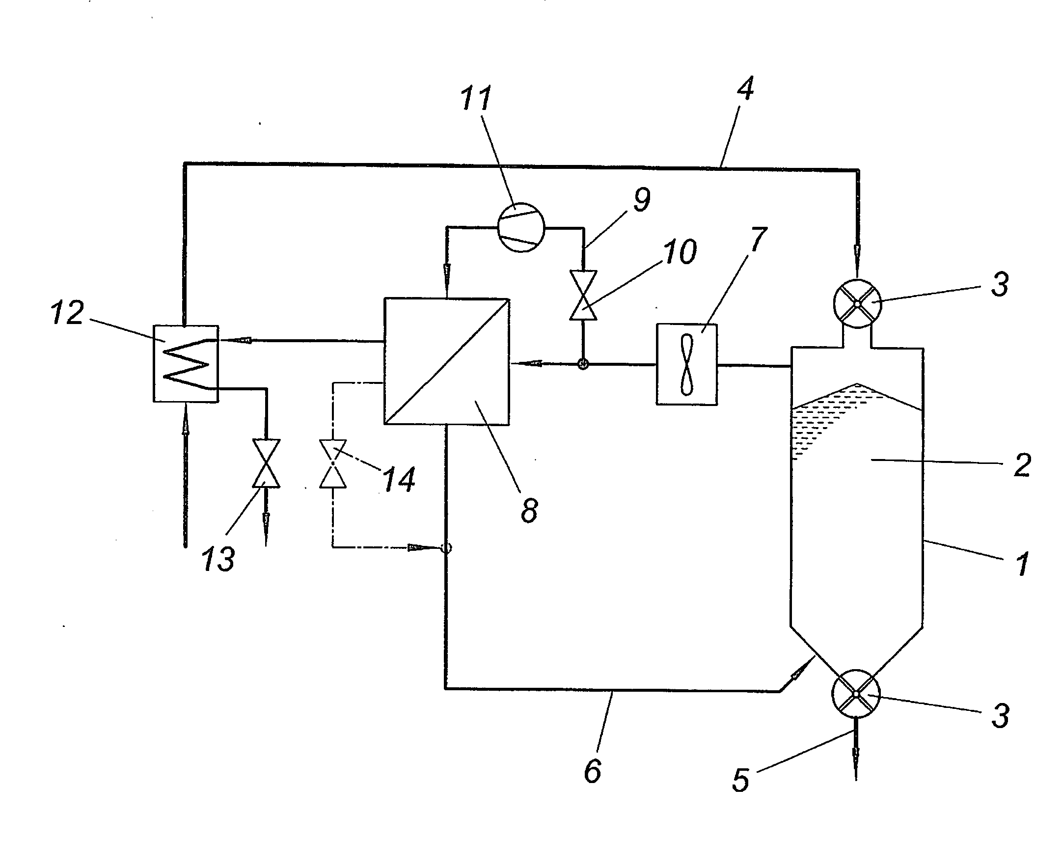
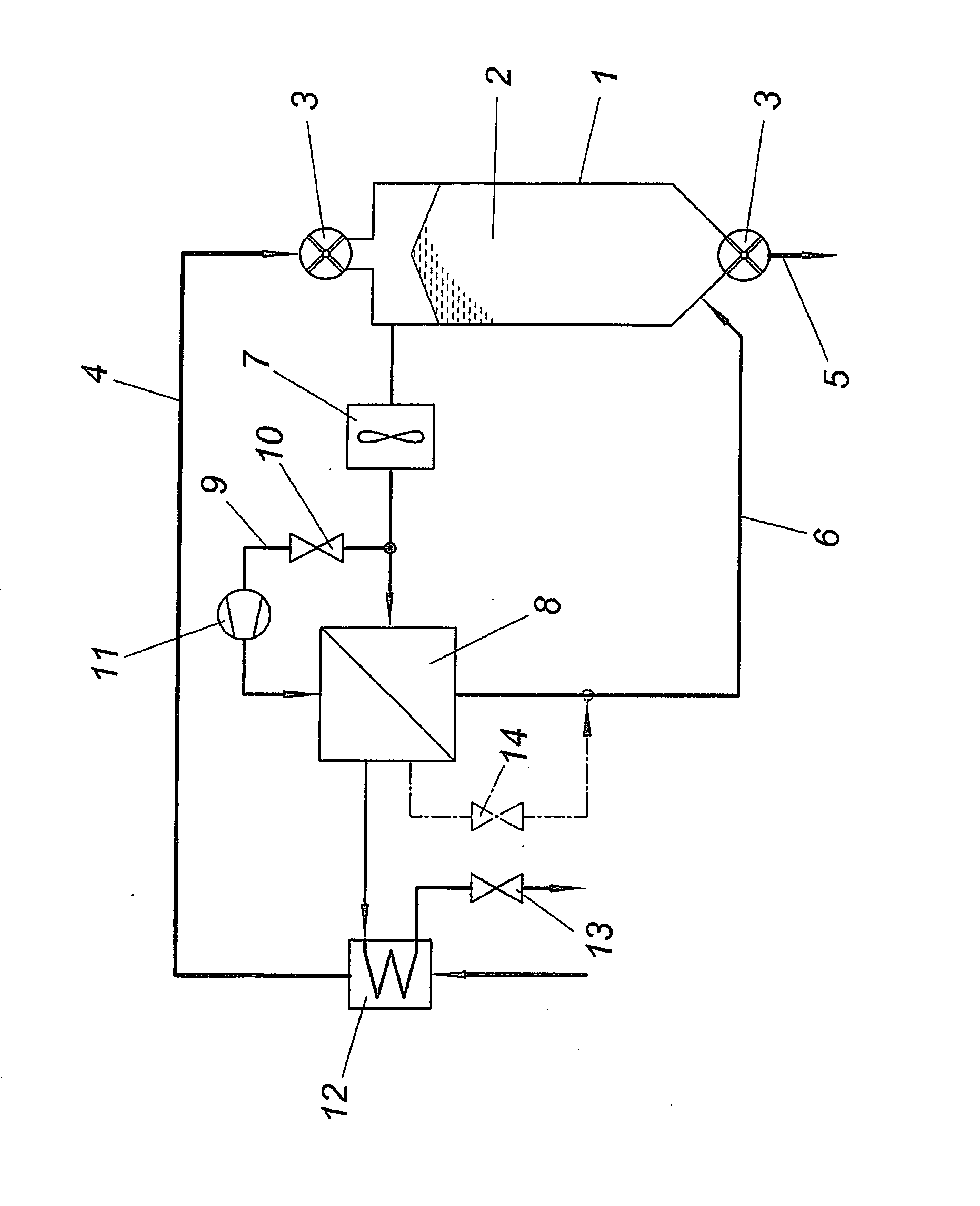
[0014]The apparatus shown for drying a material to be dried comprises a drying container 1 for the material to be dried which is conveyed continuously through the drying container 1 in the form of bulk material 2 via locks 3 on the inlet and outlet side, in the present case rotary valves. The inlet line for the material to be dried is designated by 4. The dried material is removed from the drying container 1 via an outlet line 5.

[0015]For drying the bulk material 2, the drying chamber of the drying container 1 is acted upon by a drying gas. For this purpose the drying container 1 is connected to a circulating system 6 for a drying gas stream which comprises a fan 7 for circulating conveyance of the drying gas and a heat exchanger 8 for heating the drying gas stream removed from the drying container 2. This heat exchanger 8 is acted upon by a partial stream of the drying gas which is removed via a branch line 9 of the circulating system 6 via a metering valve 10 and is brought to a h...


PUM


Abstract

A method for drying a material to be dried is described, which is acted upon inside a drying chamber by a drying gas guided in a circuit and heated by means of a heat exchanger (8) to remove the evaporated liquid. In order that a low external energy input is sufficient, it is proposed that a part of the drying gas stream is separated from the circuit, compressed and condensed in the heat exchanger (8) whilst releasing heat to the drying gas stream guided in the circuit.

Description

FIELD OF THE INVENTION[0001]The invention relates to a method for drying a material to be dried which is acted upon inside a drying chamber by a drying gas guided in a circuit and heated by means of a heat exchanger to remove the evaporated liquid.DESCRIPTION OF THE PRIOR ART[0002]For drying moist solids it is usual to act upon the material to be dried with a preferably preheated drying air stream and remove the moisture to be evaporated from the material to be dried with the drying air stream. In order to be able to advantageously dry fine-grained material, it has already been proposed to guide the drying gas stream, air or an inert gas, for example, nitrogen, in the circuit via drying containers (US 3 599 344 A) through which the material to be dried is conveyed continuously via locks on the inlet and outlet side in the opposite direction to the drying gas stream. To accelerate the drying process the material to be dried is heated with the aid of heat exchangers inside the drying ...

Claims


Application Information

Patent Timeline
Patent Type & Authority Applications(United States)
IPC IPC(8): F26B5/00
CPCF26B17/14Y02B30/52F26B23/004F26B21/086Y02P70/10
Inventor GROISBOCK, FRANZ
Owner GROISBOCK FRANZ
Why Eureka
Try Eureka