Cam shaft phase setter comprising a control valve for hydraulically adjusting the phase position of a cam shaft

a technology of cam shaft and control valve, which is applied in the direction of mechanical equipment, machines/engines, engine components, etc., can solve the problems of increased design expense and significant additional costs, difficult to configure the channels, and high cost of channel guides, and achieve cost-effective effects

Inactive Publication Date: 2011-09-15
SCHWABISCHE HUTTENWERKE AUTOMOTIVE CMBH
View PDF7 Cites 24 Cited by
  • Summary
  • Abstract
  • Description
  • Claims
  • Application Information

AI Technical Summary

Benefits of technology

It is an object of the invention to provide a cost-effective cam shaft phase setter which is suitable for mass-production and combines the advantages of a space-saving and preferably centrally arranged control valve—centrally in relation to a stator-rotor arrangement ...

Problems solved by technology

However, applying the pressure oil in this way entails channel guides which are expensive to produce, in particular P-type conduction.
It is also difficult to configure the channels with large channel cross-sections, which are favourable for high adjusting speeds.
The different oil feeds and oil drains to and from the control valve are separated from each other by means of shaft sealing rings, which however causes increased design expense and significant additional costs, resulting for instance in increased demands on the tolerances for the components which determine the radial positio...

Method used


Image

  • Cam shaft phase setter comprising a control valve for hydraulically adjusting the phase position of a cam shaft
  • Cam shaft phase setter comprising a control valve for hydraulically adjusting the phase position of a cam shaft
  • Cam shaft phase setter comprising a control valve for hydraulically adjusting the phase position of a cam shaft

Examples


Embodiment Construction

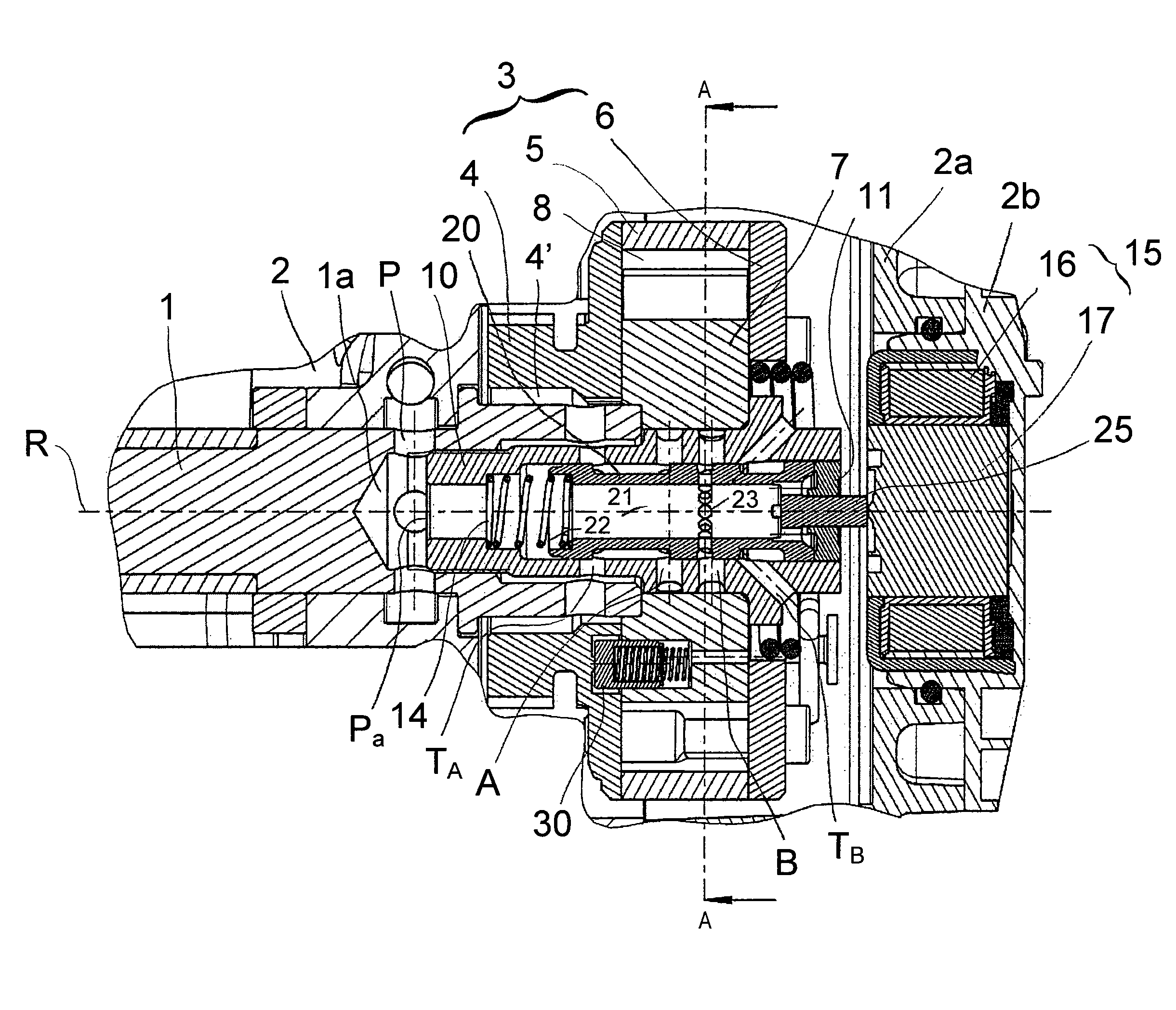
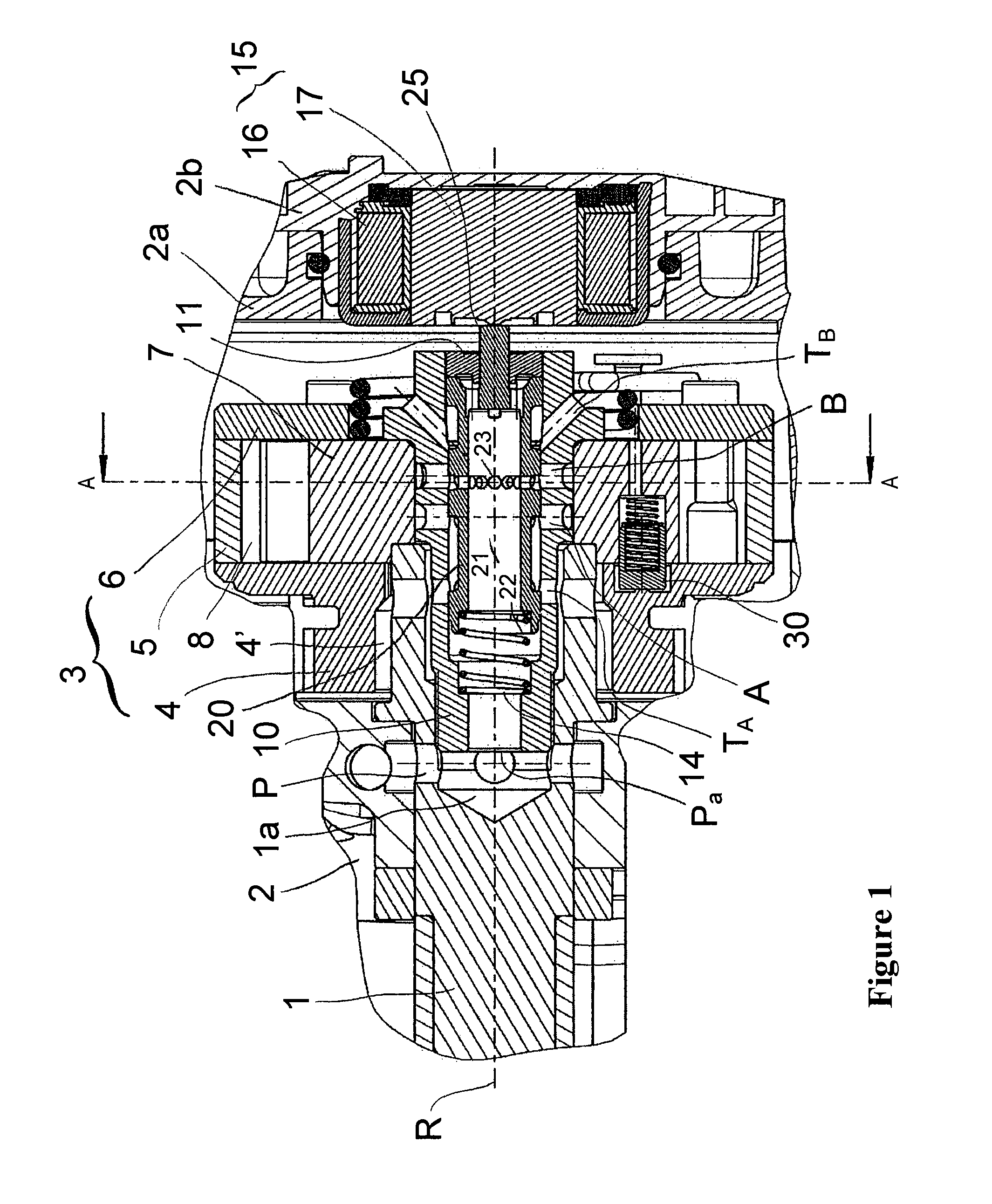
FIG. 1 shows a cam shaft phase setter in a longitudinal section. The cam shaft phase setter is arranged at an end of a cam shaft 1 on the axially facing side and serves to adjust the phase position, i.e. the rotational angular position, of the cam shaft 1 relative to a crankshaft of an internal combustion engine, for example a drive motor of a motor vehicle. The cam shaft 1 is rotatably mounted such that it can be rotated about a rotational axis R in an engine housing 2 of the internal combustion engine, usually in a cylinder head housing.

The cam shaft phase setter comprises a stator 3 which can be rotary-driven by the crankshaft, and a rotor 7 which is connected, rotationally fixed, to the cam shaft 1. The stator 3 is composed of a drive wheel 4, for example a sprocket, a cover 6 and an impeller wheel 5 which is axially arranged between the drive wheel 4 and the cover 6. The drive wheel 4, the impeller wheel 5 and the cover 6 are connected, rotationally fixed, to each other. The st...


PUM


Abstract

A cam shaft phase setter including a control valve for controlling the feeding and draining of a hydraulic fluid into and out of a pressure chamber which serves to adjust the rotational angular position of a cam shaft relative to a crankshaft of an internal combustion engine. The control valve includes a valve housing with an operating port to the pressure chamber and a reservoir port to a reservoir for the fluid. A valve piston is axially adjustable back and forth in the valve housing between a first position and a second position and includes an axial hollow space, a piston inlet for introducing the fluid into the hollow space, and a piston outlet which leads out of the hollow space and is connected to the operating port in the first position of the valve piston and separated from the operating port in the second position of the valve piston. An actuating unit is coupled to the valve piston for axially adjusting the valve piston. A coupling member protrudes through an axially facing closure wall which closes off the valve housing and couples the actuating unit to the valve piston. The valve piston includes a radial widening which is surrounded by a complementarily widened housing portion of the valve housing and to which the fluid can be applied in an axial direction pointing away from the axially facing closure wall in order to generate an axial pressure force. The widening is dimensioned such that the fluid acts on the valve piston with a pressure force of at least substantially equal size in both axial directions, despite the coupling member.

Description

CROSS REFERENCE TO RELATED APPLICATIONSThis application claims priority to German Patent Application No. 10 2010 002 713.8 filed on Mar. 9, 2010, the contents of which are incorporated herein by reference.FIELD OF THE INVENTIONThe invention relates to a cam shaft phase setter comprising a control valve for hydraulically adjusting the phase position of a cam shaft relative to a crankshaft of an internal combustion engine. The invention relates to the cam shaft phase setter itself and also to an internal combustion engine with the cam shaft phase setter mounted. The internal combustion engine can in particular be a drive motor for or in a motor vehicle.BACKGROUND OF THE INVENTIONIn order to increase output and torque, but also in order to reduce the fuel consumption and exhaust emissions of internal combustion engines for road vehicles, cam shaft phase setters for varying the inlet or outlet control times have become widespread. Hydraulic phase setters which can be operated using engi...

Claims


Application Information

Patent Timeline
IPC IPC(8): F01L1/344
CPCF01L1/3442F01L2001/34433F01L2001/34426F01L2001/3443F01L2001/34446F01L2001/3445Y10T74/2102
Inventor WELTE, CLAUSMEINIG, UWEBOHNER, JUERGEN
Owner SCHWABISCHE HUTTENWERKE AUTOMOTIVE CMBH
Why Eureka
Try Eureka