
Membranes With Functionalized Carbon Nanotube Pores For Selective Transport

a carbon nanotube and selective transport technology, applied in the direction of membranes, filtration separation, separation processes, etc., can solve the problems of large applied pressure, unsuitable for most human use, complex macromolecular nature of these biological machines, etc., and achieve the effect of improving the transport of desalted water

Active Publication Date: 2011-09-15
LAWRENCE LIVERMORE NAT SECURITY LLC
View PDF27 Cites 79 Cited by
  • Summary
  • Abstract
  • Description
  • Claims
  • Application Information

AI Technical Summary

Benefits of technology

[0016]In another aspect, there is provided a membrane for an enhanced transport of desalted water from salted water comprising, consisting essentially of, or consisting of: a substantially vertically-aligned array of carbon nanotubes, wherein the nanotubes have average pore size of about 1-2 nm having at least one functionalized nanotube and a matrix material disposed between the carbon nanotubes.
[0017]In yet another aspect, there is provided a membrane for an enhanced transport of desalted water from salted water comprising, consisting essentially of, or consisting of: a substantially vertically-aligned array of carbon nanotubes, wherein the nanotubes have average pore size of about 1-2 nm with a charge density of about 1-3 mM and have at least one functionalized nanotube; and a matrix material disposed between the carbon nanotubes.

Problems solved by technology

Despite progress made in recent decades, the complex macromolecular nature of these biological machines still complicates the understanding of the underlying mechanisms responsible for fast mass transport, selectivity, gating, and the functional role of hydrophobic pore lining and charged functionalities.
Seawater has high salinity, which makes it unsuitable for most of human use, therefore seawater needs to be separated from its salt content in the desalination process.
Salt transport occurs in a similar fashion; however, the driving force for transport is mainly the concentration gradient and the salt flux is insensitive to the pressure gradient.
Thus, to achieve good water fluxes and high salt rejection, a very large applied pressure is required.
As a consequence, the energy cost associated to the separation process is large.
Also, these membranes may tend to foul easily.

Method used


Image

  • Membranes With Functionalized Carbon Nanotube Pores For Selective Transport
  • Membranes With Functionalized Carbon Nanotube Pores For Selective Transport
  • Membranes With Functionalized Carbon Nanotube Pores For Selective Transport

Examples


example 1

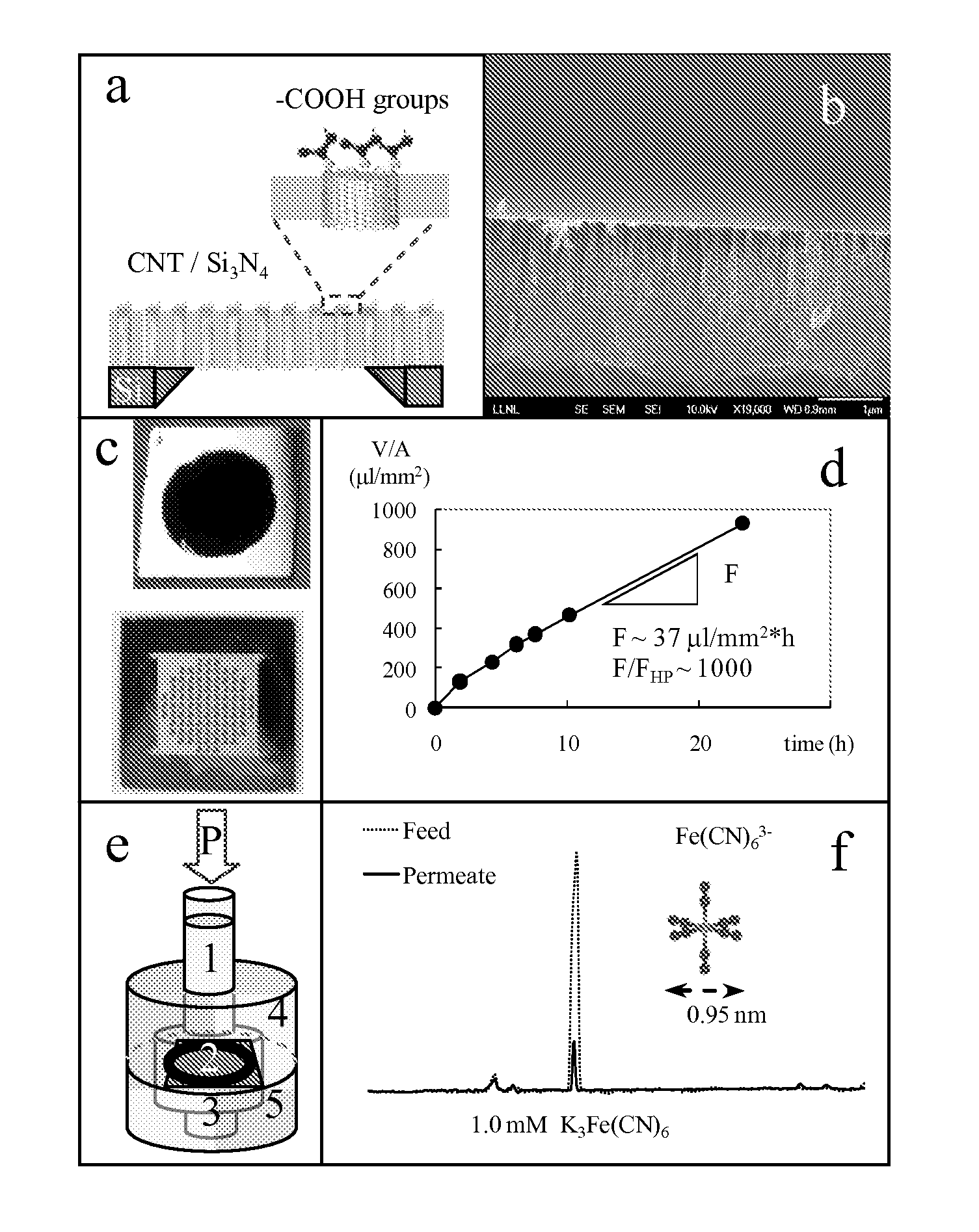
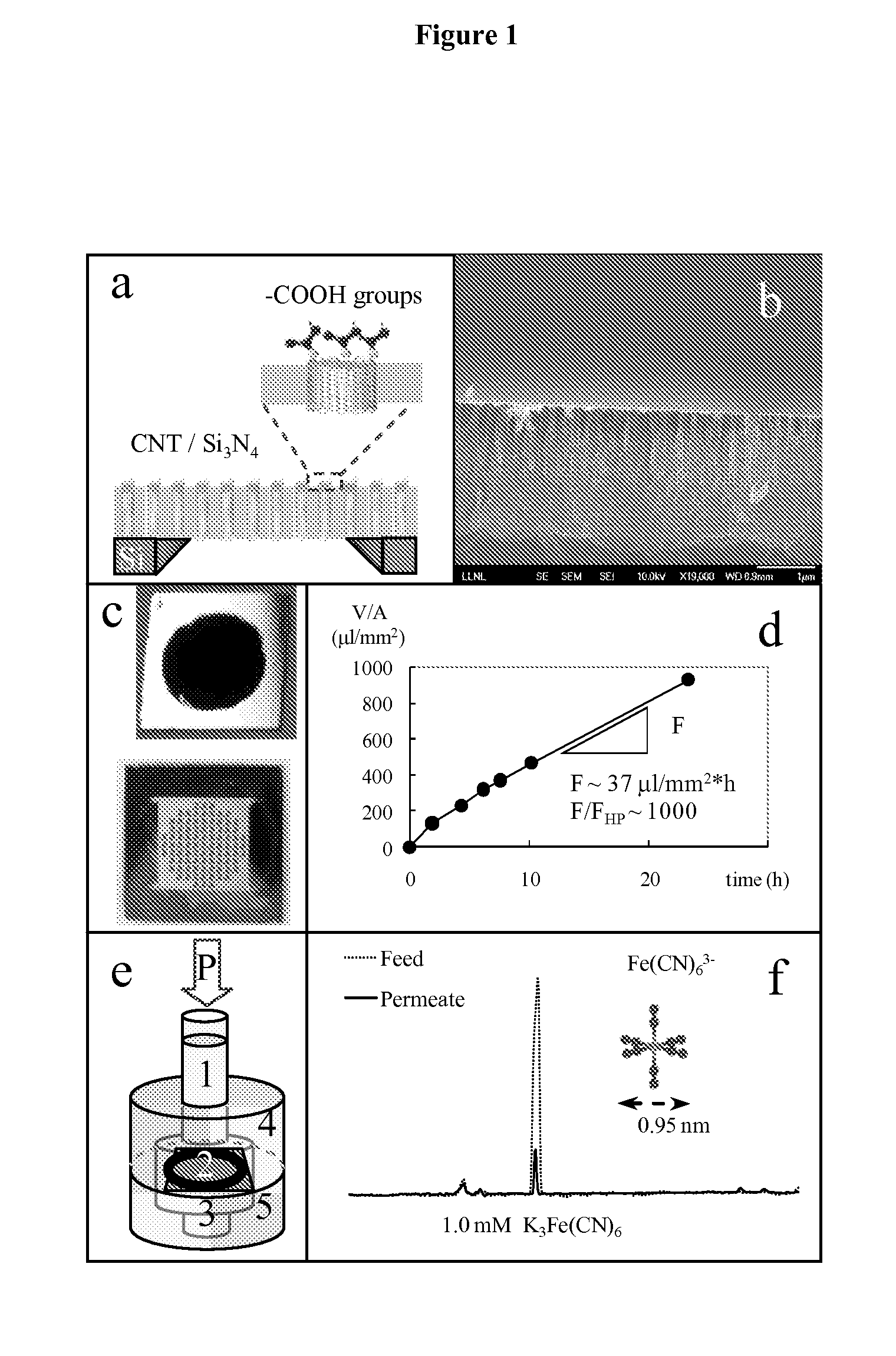
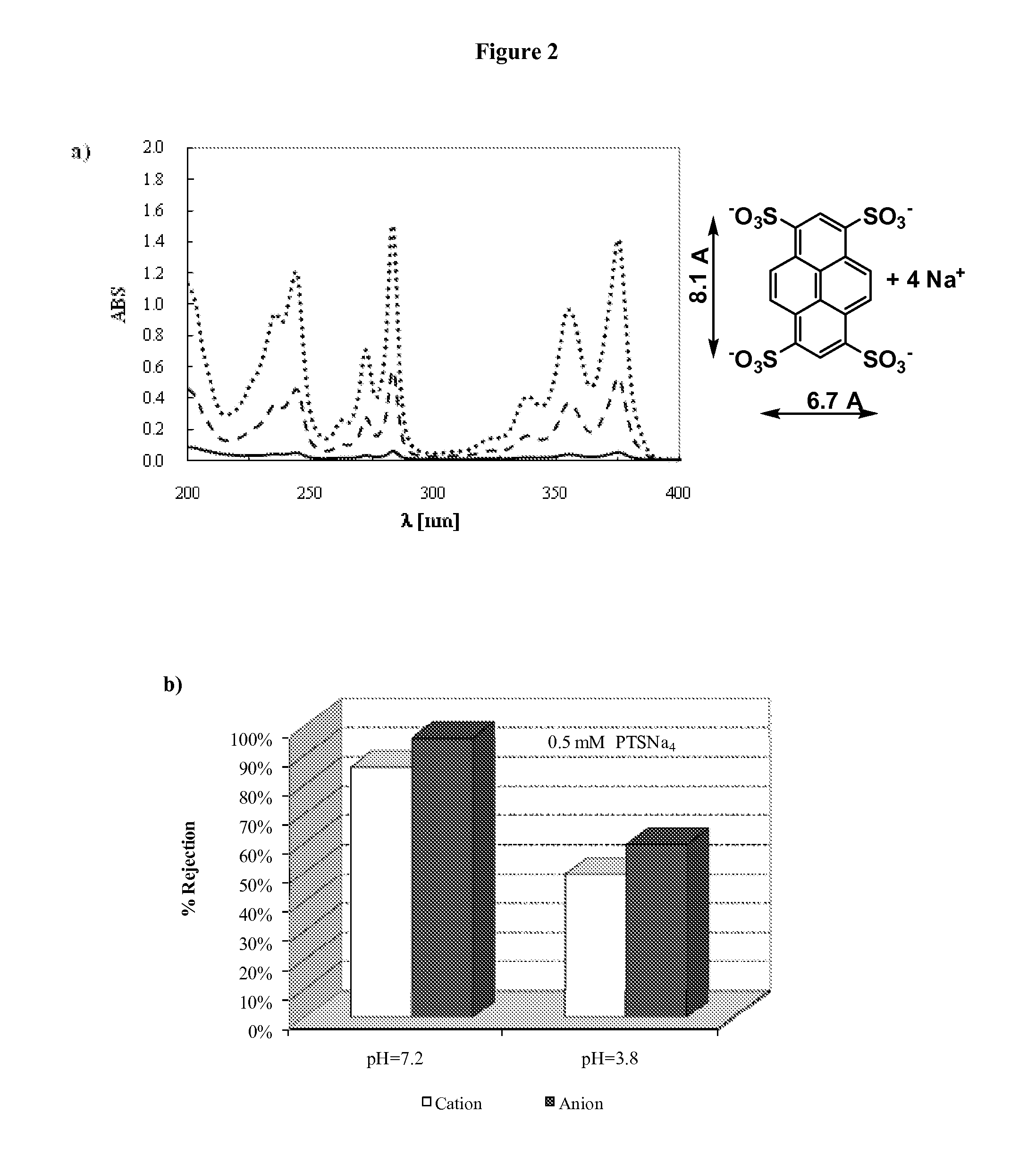
[0217]In this study, nanofiltration experiments are used to quantify ion exclusion in the sub-2-nm carbon nanotube pores and to investigate the fundamental mechanisms governing ion transport and ion exclusion in this system. Charged nanochannels can utilize both steric hindrance and electrostatic repulsion to achieve ion rejection (Schaep J, Van der Bruggen B, Vandecasteele C, Wilms D (1998) Influence of ion size and charge in nanofiltration. Sep Purif Technol 14:155-162; Schaep J, Vandecasteele C, Mohammad A W, Bowen W R (2001) Modelling the retention of ionic components for different nanofiltration membranes. Sep Purif Technol 22-3:169-179; and Childress A E, Elimelech M (2000) Relating nanofiltration membrane performance to membrane charge (clectrokinetic) characteristics. Environ Sci Technol 34:3710-3716). To understand the relative importance of these rejection mechanisms, ion exclusion and selectivity as a function of solution concentration, pH, ion valence, and ion size is in...

example 2

[0262]Preliminary experimental data suggest that the DWNT-SiN membranes with CNT tip attached with carboxylic groups outperform typical commercial nanofiltration membranes (without carbon nanotubes) for water softening by providing much larger fluxes at similar monovalent salt rejection or, vice versa, by enabling significantly larger salt rejection at similar water fluxes. For example, a DWNT-SiN membrane rejected 40% of the ion content when a 1 mM KCl solution was filtered at a feed pressure of 10 psi. The corresponding water flux was about 0.63 μl / mm2 min. At the same conditions, Filmtec NF90 and NF270 rejected 35% and less that 10% of the salt, respectively, while allowing water fluxes 5 and 2 times smaller than for the DWNT-SiN membranes. FIG. 7 shows nanofiltration of 1 mM KCl solution at 10 psi. a) rejection coefficient and b) water fluxes measured for DWNT membranes, and commercial nanofiltration membranes NF90 and NF270.

[0263]The comparatively high rejection of the DWNT-SiN...

example 3

Nanofiltration Experiment for Binary Salt Solutions

[0264]Binary KCl / K2SO4 salt solutions with desired composition and constant equivalent concentration were prepared by mixing appropriate amounts of 1 mM KCl and 0.5 mM K2SO4 stock solutions.

[0265]The top chamber (feed) of the filtration cell was filled with about 2 ml of binary salt solution, while the bottom chamber (permeate) was sealed with a small vial containing 1 ml of distilled water to limit permeate evaporation before the analysis of ion concentration. The feed solution was pressurized at 0.69 bar with a controlled nitrogen gas line, while the permeate was at atmospheric pressure. After 150-200 μL of solution had permeated through the CNT membrane, samples from both feed and permeate were collected for subsequent analysis by capillary electrophoresis (CE). Rejection coefficients for Cl− and SO42− anions were obtained from the ratio of resolved-peak area of the corresponding ion in the CE chromatogram for permeate and feed s...


PUM

PropertyMeasurementUnit
Lengthaaaaaaaaaa
Lengthaaaaaaaaaa
Fractionaaaaaaaaaa

Abstract

Provided herein composition and methods for nanoporous membranes comprising single walled, double walled, or multi-walled carbon nanotubes embedded in a matrix material. Average pore size of the carbon nanotube can be 6 nm or less. These membranes are a robust platform for the study of confined molecular transport, with applications in liquid and gas separations and chemical sensing including desalination, dialysis, and fabric formation.

Description

CROSS REFERENCE TO RELATED APPLICATIONS[0001]This application claims priority under 35 U.S.C. §119(e) of U.S. Provisional Application No. 61 / 056,940, filed on May 29, 2008, which is hereby incorporated by reference in its entirety.[0002]The United States Government has rights in this invention pursuant to Contract No. DE-AC52-07NA27344 between the United States Department of Energy and Lawrence Livermore National Security, LLC for the operation of Lawrence Livermore National Laboratory.FIELD OF THE INVENTION[0003]Provided herein are carbon nanotubes membranes and nanofiltration membranes whose through-pores are made of sub-6 nm carbon nanotubes with entrance modified by functional groups. Charges at the pore entrance and the small diameter of the pores ensures that these membranes are able to efficiently exclude ions and small molecules while maintaining ultra-fast fluid permeation.BACKGROUND OF THE INVENTION[0004]Ion transport across cellular membranes is essential to many of life'...

Claims


Application Information

Patent Timeline
IPC IPC(8): B01D61/00B01D29/00B82Y99/00
CPCA61M1/34Y02C10/10B01D61/025B01D61/027B01D67/0072B01D67/0079B01D69/148B01D71/02B01D71/021B01D71/024B01D71/027B01D2256/10B01D2256/22B01D2256/24B01D2257/102B01D2257/504B01D2323/36B01D2325/18B82Y30/00C02F1/44C02F1/442C02F2103/08C02F2305/08B01D53/228A61M2205/3306A61M1/341Y02A20/131Y02C20/40B01D71/0212B01D71/0215B01D67/00793
Inventor BAKAJIN, OLGICANOY, ALEKSANDRFORNASIERO, FRANCESCOPARK, HYUNG GYUHOLT, JASON K.KIM, SANGIL
Owner LAWRENCE LIVERMORE NAT SECURITY LLC
Learn More