Temperature information output apparatus, imaging apparatus, method of outputting temperature information

a technology of temperature information and output apparatus, which is applied in the field of temperature information output apparatus, imaging apparatus, and method of outputting temperature information, can solve the problems of easy generation of errors and difficulty in obtaining a sufficiently high precision, and achieve the effect of high precision

Inactive Publication Date: 2011-09-15
SONY CORP
View PDF2 Cites 31 Cited by
  • Summary
  • Abstract
  • Description
  • Claims
  • Application Information

AI Technical Summary

Benefits of technology

[0020]According to the embodiments of the present invention, it is possible to prevent a chip area where circu

Problems solved by technology

For this reason, it may be difficult to obtain a sufficiently high precision, and it may be easy to generate errors due to a process variation.
However, in this case, it is necessary to separately provide an ADC capable of ac

Method used


Image

  • Temperature information output apparatus, imaging apparatus, method of outputting temperature information
  • Temperature information output apparatus, imaging apparatus, method of outputting temperature information
  • Temperature information output apparatus, imaging apparatus, method of outputting temperature information

Examples


first embodiment

1. First Embodiment

[Configuration Example of Imaging Apparatus]

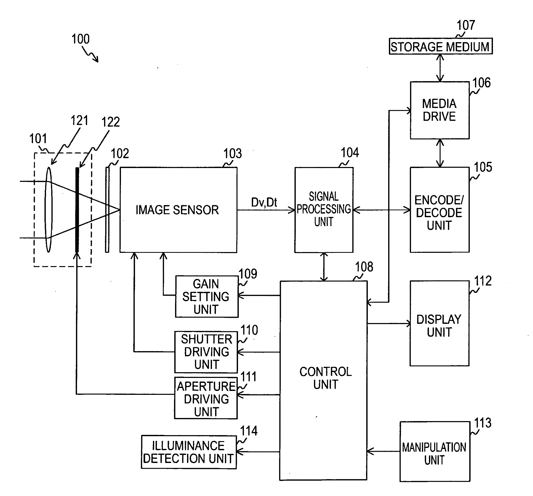
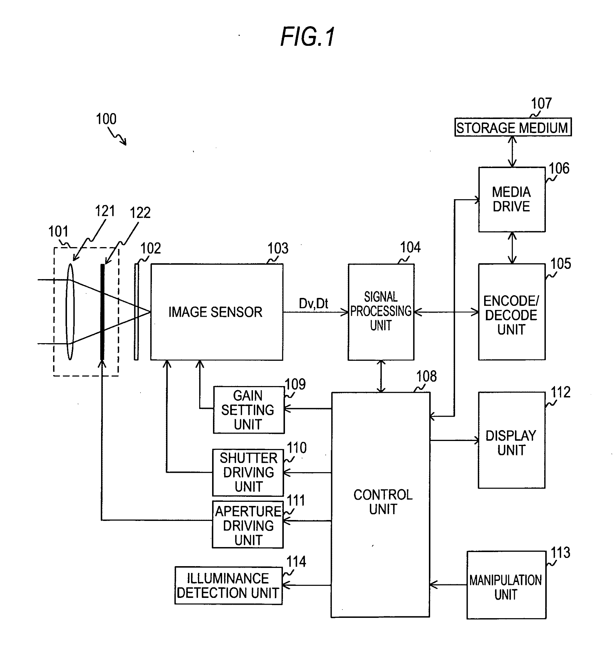
[0040]FIG. 1 is a block diagram illustrating a configuration example of the imaging apparatus 100 according to a first embodiment of the invention. The imaging apparatus 100 shown in this drawing can store the image obtained through image capturing in a storage medium as moving picture data or still image data. In addition, the configuration of the imaging apparatus 100 shown in this drawing is common to a second embodiment of the invention, which will be described below.

[0041]The imaging apparatus 100 shown in this drawing includes an optical system unit 101, a filter 102, an image sensor 103, a signal processing unit 104, an encode / decode unit 105, and a media drive 106. In addition, the imaging apparatus 100 further includes a control unit 108, a gain setting unit 109, a shutter driving unit 110, an aperture driving unit 111, an illuminance detection unit 114, a display unit 112, and a manipulation unit 113.

[0042]The ...

second embodiment

2. Second Embodiment

[Example of Gain Change]

[0165]The imaging apparatus 100 according to the embodiment of the invention may be provided with a function capable of changing the gain for the image data (signal) read from the image sensor 103. The second embodiment provides an image sensor 103 configured to obtain suitable temperature information for the case that the imaging apparatus 100 employs such a variable gain configuration.

[0166]First, an example of gain change for the image data executed by the imaging apparatus 100 will be described with reference to FIGS. 10A to 10C.

[0167]As the imaging apparatus 100 performs automatic exposure (AE) control, first, the illuminance detection unit 114 detects illuminance, and the control unit 108 specifies, for example, a shutter speed and an aperture value based on the detected illuminance and performs control to provide the shutter speed and the aperture value specified above. It is noted that, as the shutter speed becomes lower, the recei...


PUM


Abstract

A temperature information output apparatus includes: a first comparison unit provided to match with a specific row in a pixel array unit and receiving and comparing an analog pixel signal output from a pixel and a reference signal having a ramp waveform having a predetermined inclination and a signal period; a first count unit carrying out a count operation during a count period within a reset period and a count period within a signal period; a first data output unit outputting the pixel data based on a count value obtained by the first count unit; a local voltage/temperature signal generating unit generating a local voltage and a temperature signal; a second comparison unit receiving and comparing the temperature signal and the reference signal; a second count unit carrying out a count operation during a count period within a reset period and a count period within a signal period; and a second data output unit outputting temperature data based on a count value obtained by the second count unit.

Description

BACKGROUND OF THE INVENTION[0001]1. Field of the Invention[0002]The present invention relates to a temperature information output apparatus, and more particularly, to a temperature information output apparatus, an imaging apparatus, and a method of outputting temperature information, by which a temperature is detected from an imaging device to output temperature information.[0003]2. Description of the Related Art[0004]Sometimes, in electronic apparatuses, a circuit or device may be configured to detect a temperature and output the resulting temperature information, for example, in order to compensate for temperature characteristics of elements included in the circuit and obtain stable operations.[0005]As an exemplary configuration for outputting the temperature information, there is known an example using a temperature characteristic of a diode. For example, there is known a solid-state imaging device such as a complementary metal oxide semiconductor (CMOS) image sensor using a temp...

Claims


Application Information

Patent Timeline
IPC IPC(8): H04N5/235G01K7/00
CPCG01K7/01G01K2219/00H04N5/37457H03M1/56H03M1/089H03M1/123H03M1/0621H04N25/778
Inventor WAKABAYASHI, HAYATOHARA, MASATOSHI
Owner SONY CORP
Why Eureka
Try Eureka