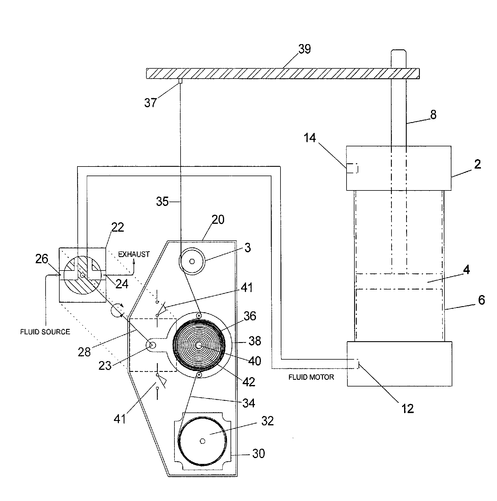
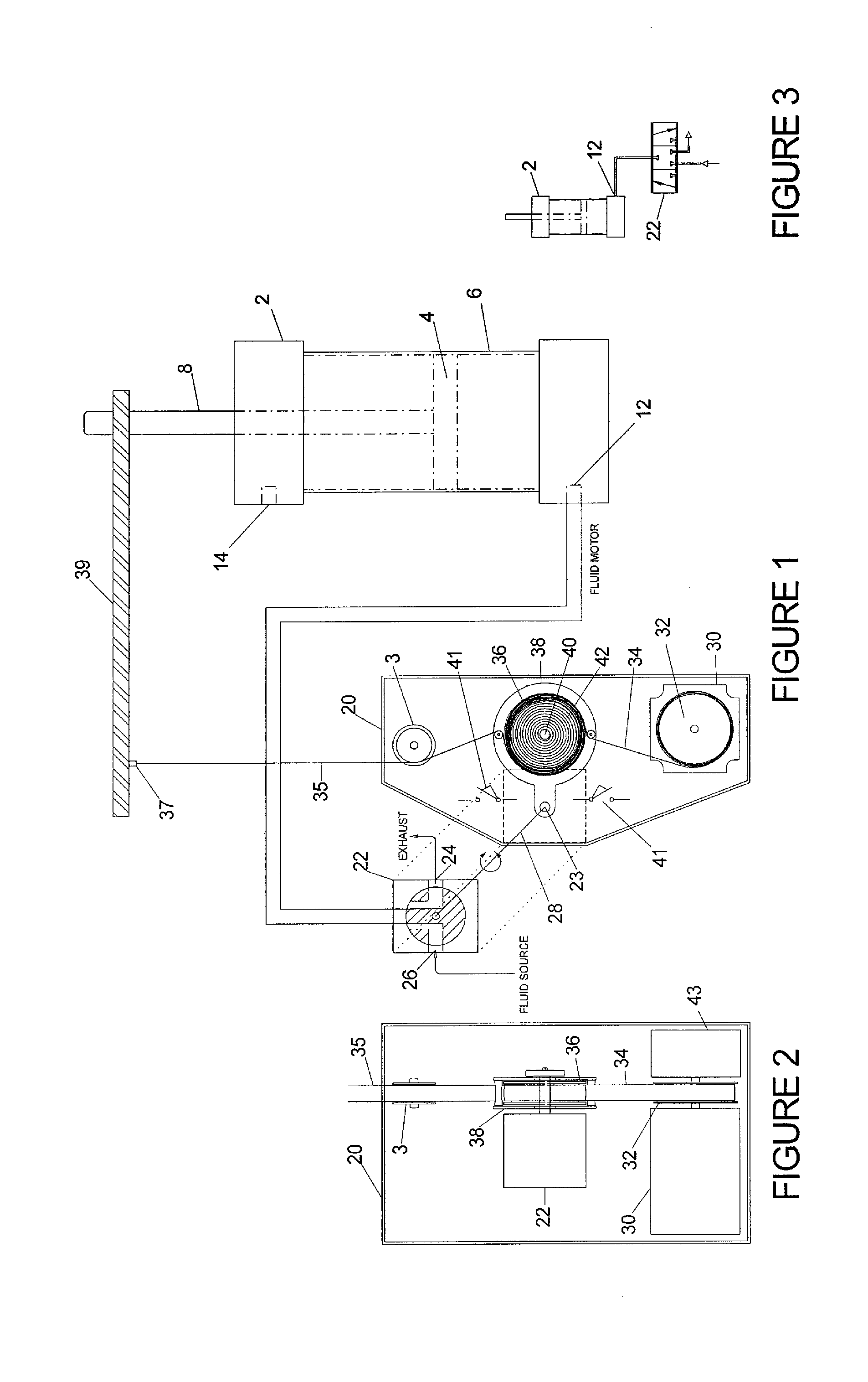
[0010]The invention is directed to a control
system for a fluid motor that includes an electronically controlled positioning (
stepper) motor, a self-storing mechanical feedback /
valve actuator assembly and a mechanically controlled valve. It can be used to position a fluid motor that is either hydraulically or pneumatically powered. The feedback /
valve actuator section is capable of providing accurate positioning of a fluid motor. A characteristic of the invention is that when the
stepper-driven “command” spool is prevented from rotating by a spring-applied
brake, the feedback /
valve actuator device remains active after
electric power is turned off. This is true as long as
fluid pressure and flow capacity are supplied to the inlet of the valve. This attribute enables the invention to hold a pneumatic fluid motor in position indefinitely; while making position corrections to compensate for changes in
air compression should any changes in the load pressure occur. Another characteristic is the low cost and simplicity of the components of which the device is comprised.
Stepper motors and their controllers are widely used internationally and as such, have a low price point. Command, feedback, position-error summing and power amplification are performed by an exceedingly simple mechanical device within the invention. Another characteristic is the hardy resistance of the mechanical feedback line to detriment by hostile environments. Another characteristic is the flexibility of the feedback line, which enables it to be attached to loads that travel a curved path. Still another characteristic is that several fluid motors, each outfitted with the invention, can be positioned in exact synchronization, or in ratio synchronization, to each other and other devices by means of a master electronic controller. A simple housing contains the
stepper motor, take up spool, holding
brake and fluid
motor control valve for ease of installation and use. The electronic command source is a
stepper motor controller, which provides position and speed control to the
stepper motor. This controller may be remotely located or built within the motor. It communicates with and sends position commands to the stepper either by wires or wirelessly.
Stepper motors may be run in open or
closed loop control architectures. Rather than its common use as an
output device to perform work, the
stepper motor in this invention is a
signal converter. It transforms an electronic position command into a mechanical servo input
signal. This
signal is the command input for the servo. The stepper motor is operatively connected to a take up spool for positioning a command tension line wound there upon.
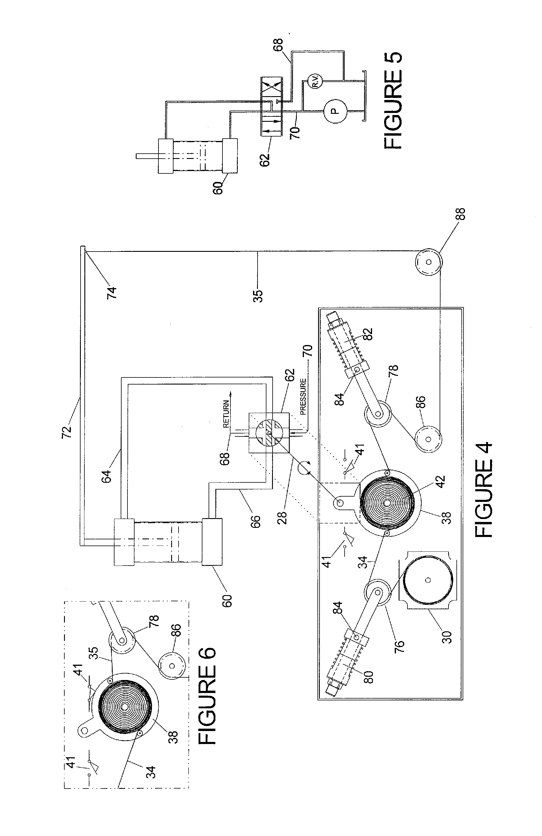
[0012]A
torsion spring biases the spool to rotate so as to wind both lines onto its surface. The spring-biased spool is moveable and in operative relationship with a valve
actuator. The valve
actuator will operate to control a
fluid control valve to position the fluid motor. At rest, with the stepper motor at standstill, the spring-biased spool exerts a force that is equally shared by the command and
tension lines. In this state, the fluid valve is in a null position. In the null position, the valve directs exactly the volume of fluid to create the required pressure to hold the fluid motor in a stationary position. When a rotational change is made to the stepper's shaft, the balance of forces between the command and
tension lines changes. This imbalance causes a reaction force, which moves the spring-biased spool about its axis, shifting the valve. The fluid motor moves, its rate in proportion to the amount the valve is shifted. Velocity control of the fluid motor is possible within the control
system's dynamic capability. When the stepper's shaft is stopped, the spring-biased spool also stops. This causes the spring-biased spool tension to again be equally shared between the command and feedback lines and the valve
actuator returns to its null position, stopping the fluid motor. An electrical switch on either side of the self-storing mechanical servo
assembly is activated if a) either tension line fouls or breaks, or b) if the fluid motor runs ahead of or lags behind the stepper motor by an excessive amount. The electrical switch provides an input signal to the stepper controller. The stepper motor need only be of sufficient size to develop the torque necessary to overcome the biasing spring and accelerate / decelerate the spring-biased spool. In its role as a signal converter, a small stepper motor can be used to position a fluid motor of any bore size and displacement, accurately positioning loads into the tons.

