
Radial internal combustion engine with different stroke volumes

a technology of internal combustion engine and stroke volume, which is applied in the direction of positive displacement engine, bearing, shaft and bearing, etc., can solve the problems of unnecessary waste of energy, increased cost and inconvenience, etc., and achieves the effects of increasing combustion excursion, saving energy, and increasing power outpu

Inactive Publication Date: 2011-09-22
MOHTASHEMI BAHMAN
View PDF10 Cites 9 Cited by
  • Summary
  • Abstract
  • Description
  • Claims
  • Application Information

AI Technical Summary

Benefits of technology

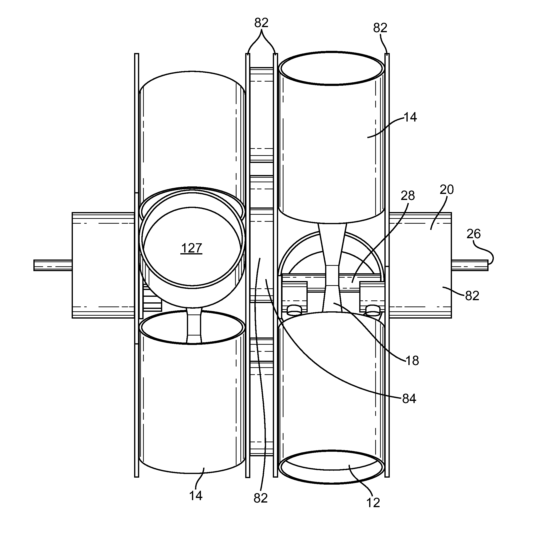
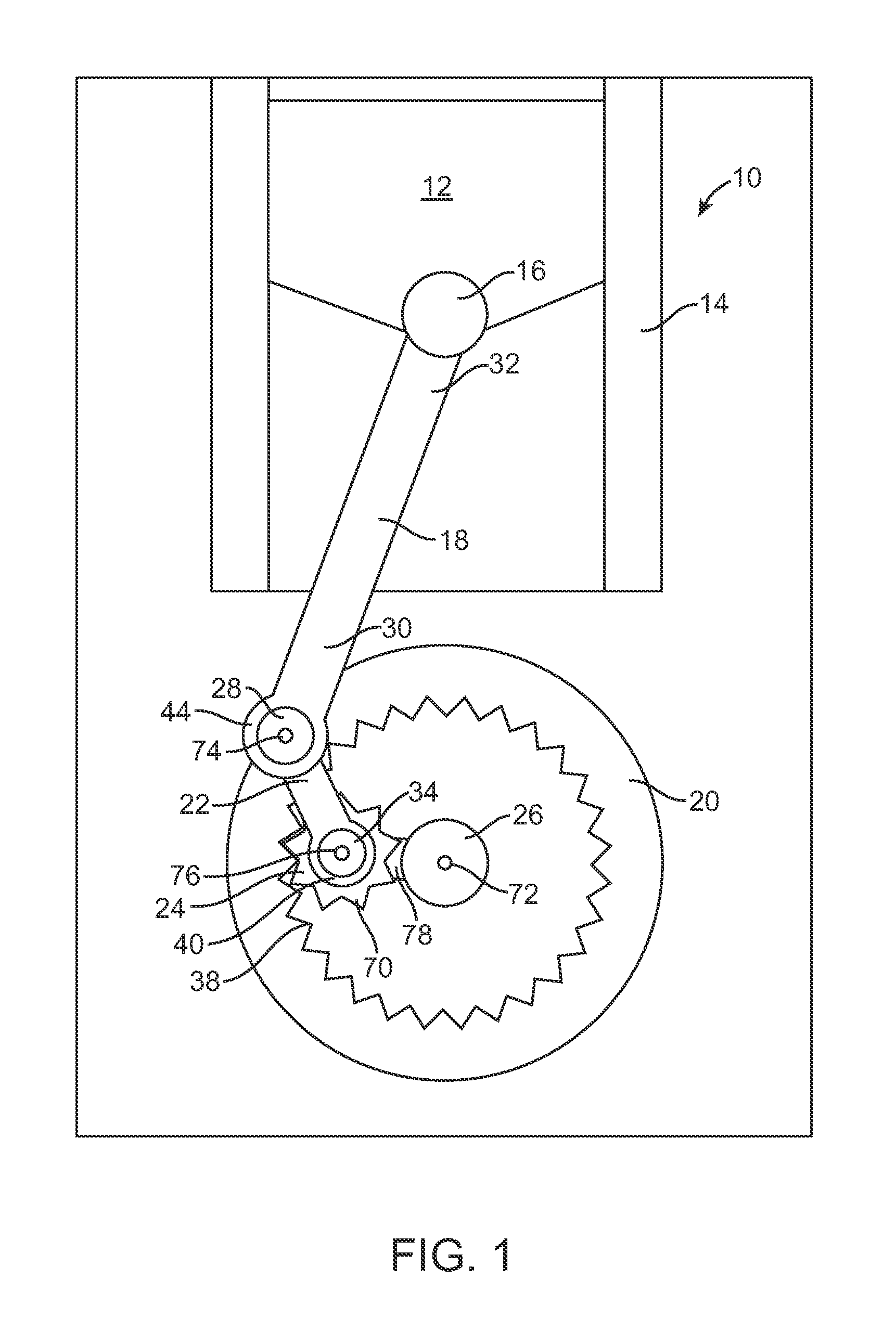
[0008]Briefly, the present invention relates generally to an internal combustion engine and more specifically to a radial internal combustion engine employing a hypocycloidal connection between the crankshaft and the piston connecting rods, creating different stroke volumes on the intake stroke and the power stroke, thus increasing combustion excursion, increasing power output and saving energy.
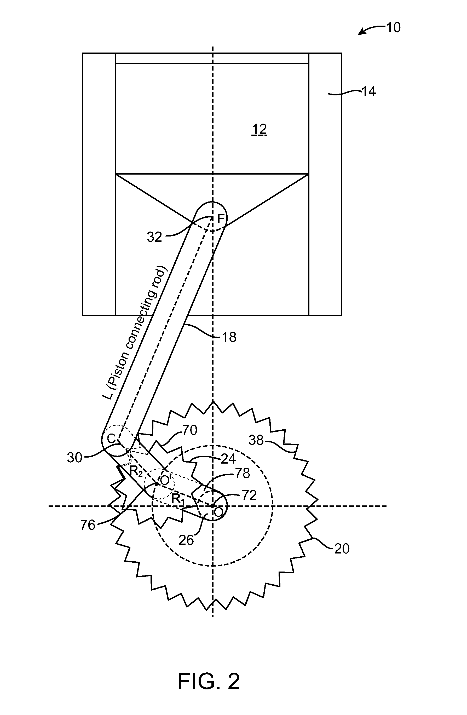
[0009]In accordance with the various embodiments of the present invention, an internal combustion engine is disclosed having a displacement during the combustion stage that is larger than the displacement during the intake stage, thereby offering the benefit of using residual energy to increase efficiency and improve fuel conservation, reducing or eliminating the requirement for a muffler and reducing cooling system requirements due to cooler expanded burnt fuel. To attain the foregoing, a hypocycloidal system includes an inner cogwheel rotating inside of an outer annular cogwheel, with the diameter and number of teeth of the inner cogwheel being exactly one third of outer cogwheel.
[0012]In another embodiment, there is provided a crankshaft assembly for a radial internal combustion four-cycle engine having at least three cylinders and a housing for the crankshaft assembly, comprising: a crankshaft disposed in the engine housing; an annular outer cogwheel mounted within the housing and being oriented concentric with the axis of rotation of the crankshaft; the crankshaft having at least one throw arm extending perpendicularly from the crankshaft axis; an inner cogwheel rotatably connected to each throw arm, engaging the annular cogwheel and having a cogshaft extending therefrom perpendicular to its axis of rotation; each cylinder having a piston disposed therein, with one end of the piston being pivotally connected to the outer end of a connecting rod; and the inner end of each connecting rod being rotatably attached to a cogshaft journal; whereby the crankshaft assembly allows the inner end of the connecting rod to move hypocycloidally with respect to the axis of the crankshaft, thus enabling a different piston displacement during the intake cycle compared to the combustion cycle of a four-cycle engine.
[0013]In yet another embodiment, there is provided a crankshaft assembly for a radial internal combustion engine having at least three cylinders and a housing for the crankshaft assembly, comprising: a crankshaft disposed in the engine housing, the housing having an integral annular cogwheel oriented concentric with the axis of rotation of the crankshaft, the crankshaft having at least one throw arm extending perpendicularly from the axis, an inner cogwheel rotatably connected to each throw arm and engaging the annular cogwheel, each cylinder having a piston disposed therein, with one end of the piston being pivotably connected to the outer end of a connecting rod, the inner end of each connecting rod being rotatably attached to a cogshaft journal which attaches perpendicular to the end of cogshaft which itself extends from the inner cogwheel perpendicular to its axis of rotation, whereby the crankshaft assembly allows the inner end of the connecting rod to move hypocycloidally with respect to the axis of the crankshaft, thus enabling a different piston displacement during the intake stroke as opposed to the combustion stroke.

Problems solved by technology

Also, the exhaust gas is forced out with considerable pressure, resulting in a loud sound, therefore undesirably requiring a muffler, which is naturally more costly and inconvenient.
In today's engines, due to necessity imposed by engine structure of all cycles being equal, during the combustion cycle (or stage), the travel of the piston cannot be regulated to desired length, resulting in an unnecessary waste of energy.

Method used


Image

  • Radial internal combustion engine with different stroke volumes
  • Radial internal combustion engine with different stroke volumes
  • Radial internal combustion engine with different stroke volumes

Examples


example 1

n=4, m=1

[0065]In this example, OFmax=4.90 R1 and appears at the angle of θ=5°. By Formulas 2 and 3, OF at end of intake=4 R1 and at the end of combustion=2 R1, so the length of intake=4.90 R1−4 R1=0.90 R1 and length of combustion=2.90 R1. Thus, the ratio of combustion to intake is (2.90 / 0.90)=3.22 and if the compression ratio is 8, expansion ratio will be 3.22×8=25.76. FIG. 8 schematically shows four different cycles of this example.

example 2

n=4, m=0.8

[0066]In this example, OFmax=4.72 R1 at angle of θ=10°, and OF at the end of intake=4.2 R1. The length of the intake stroke=0.52 R1, and the length of the combustion stroke=2.52 R1 Thus, the ratio of combustion to intake=(2.52 / 0.52)=4.84. If the compression ratio is 8, then the expansion ratio is 4.84×8=38.72.

example 3

n=3 m=1

[0067]In this example, OFmax=3.84 R1 at angle θ=4°, and OF at the end of intake=3 R1 and at the end of combustion=R1, thus, the length of the intake stroke=0.84 R1, and the length of the combustion stroke=2.84 R1. The ratio of combustion to intake lengths=(2.84 / 0.84)=3.38, and with a compression ratio of 8, the expansion ratio=3.38×8=27.


PUM


Abstract

A radial internal combustion engine employing a hypocycloidal connection between the crankshaft and the piston connecting rods, creating different stroke volumes on the intake stroke and the power stroke, thus increasing combustion excursion and saving energy.

Description

BACKGROUND OF THE INVENTION[0001]1. Field of the Invention[0002]The present invention relates generally to an internal combustion engine and more specifically to an internal-combustion engine employing reciprocating pistons in a radial design which employs a hypocycloidal connection between the crankshaft and the piston connecting rods.[0003]2. Description of the Prior Art[0004]Conventional internal combustion engines have four cycles, namely, intake, where air and vaporized fuel are drawn in; compression, where fuel vapor and air are compressed; combustion or power, where the compressed air and fuel ignite and expand and the piston is pushed downwards; and exhaust, where the exhaust is driven out. Each of these four cycles has an equal stroke distance and therefore the volume of the space through which the piston travels during a single stroke cycle, or displacement, is equal. The term “stroke distance” as used herein refers to the distance that a piston travels in one cycle.[0005]...

Claims


Application Information

Patent Timeline
IPC IPC(8): F02B75/22F02B75/04F02B75/32
CPCF02B41/04F02B75/222F01B2009/045F02B2075/1812F02B75/32
Inventor MOHTASHEMI, BAHMAN
Owner MOHTASHEMI BAHMAN
Learn More