
Converter and method for extracting maximum power from piezo vibration harvester

a technology of vibration harvester and converter, which is applied in the direction of efficient power electronics conversion, generator/motor, transportation and packaging, etc., can solve the problem of not being able to minimize the amount of waste of collected energy, and achieve the effect of avoiding large amounts of power wasted

Active Publication Date: 2011-09-22
TEXAS INSTR INC
View PDF16 Cites 48 Cited by
  • Summary
  • Abstract
  • Description
  • Claims
  • Application Information

AI Technical Summary

Benefits of technology

[0013]It is an object of the present invention to provide an improved implementation of a piezo energy harvesting system that avoids large amounts of power wasted in prior piezo energy harvesting systems.
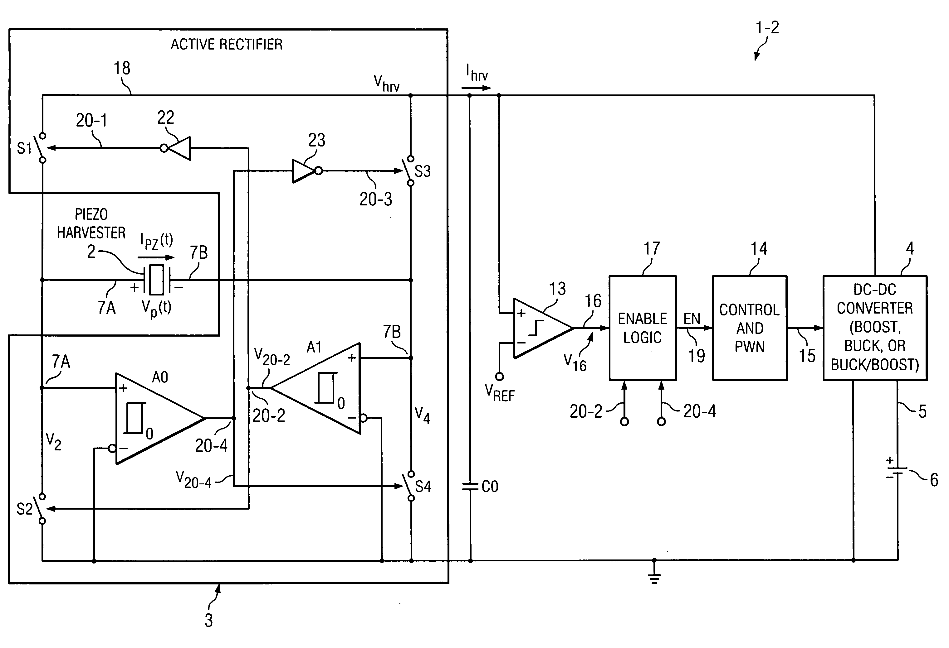
[0015]Briefly described, and in accordance with one embodiment, the present invention provides a system (1-2) for efficiently transferring harvested vibration energy to a battery (6). The system includes a piezo harvester (2) generating an AC output voltage (VP(t)) and current (IPZ(t)) and an active rectifier (3) to produce a harvested DC voltage (Vhrv) and current (Ihrv) which charge a capacitance (C0). An enable circuit (17) causes a DC-DC converter (4) to be enabled, thereby discharging the capacitance into the converter, when a comparator (A0,A1) of the rectifier which controls switches (S1-S4) of the rectifier detects a direction reversal of the AC output current (IPZ(t)). Another comparator (13) causes the enable circuit (17) to disable the converter (4) when the DC voltage exceeds a threshold (VREF), thereby causing the capacitance be recharged.
[0019]In one embodiment, the invention provides a method for efficiently transferring harvested vibration energy to a battery (6), including coupling the vibration energy to a piezo harvester (2) thereby causing the piezo harvester (2) to generate an AC output voltage (VP(t)) and an AC output current (IPZ(t)) that together constitute the harvested vibration energy; coupling the AC output voltage (VP(t)) and AC output current (IPZ(t)) to an active rectifier (3) and rectifying the AC output voltage (VP(t)) and AC output current (IPZ(t)) to produce a harvested DC output voltage (Vhrv) and a harvested DC output current (Ihrv); conducting the harvested DC output current (Ihrv) into a capacitance (C0) to charge the capacitance (C0) until the harvested DC output voltage (Vhrv) reaches a level at which a direction of the AC output current (IPZ(t)) reverses; detecting the direction reversals by means of comparators (A0, A1) in the active rectifier (3); enabling a DC-DC converter (4) in response to the detecting to cause discharging of the capacitance (C0) into an inductor (L0) of the DC-DC converter (4) in response to each direction reversal; disabling the DC-DC converter (4) in response to a comparison of the harvested DC output voltage (Vhrv) with a reference voltage (VREF) wherein the harvested DC output voltage (Vhrv,) is less than the reference voltage (VREF) to stop the discharging of the capacitance (C0) and cause recharging thereof; and enabling the DC-DC converter (4) by operating a switch (S0) of the DC-DC converter (4) to cause resulting current in the inductor (L0) to flow into the battery (6), the enabling including generating an enable signal (EN) by operating a state machine (17, FIG. 5) having a first state (A) in which the enable signal (EN) is at a logical “1” level to enable the DC-DC converter (4) and a second state (B) wherein the enable signal (EN) is at a logical “0” level to disable the DC-DC converter (4), wherein the state machine (17) switches from the first state (A) to the second state (B) in response to an output (V16) generated by comparator (13) that performs the comparison going from a “1” level to a “0” level, and wherein the enable logic circuit (17) switches from the second state (B) to the first state (A) in response to the detecting of the direction reversal.
[0021]In one embodiment, the method provides a system (1-2) for efficiently transferring harvested vibration energy to a battery (6), including piezo harvester means (2) for receiving the vibration energy and a generating an AC output voltage (VP(t)) and an AC output current (IPZ(t)) that together constitute the harvested vibration energy; means (18) for coupling the AC output voltage (VP(t)) and AC output current (IPZ(t)) to active rectifier means (3) for rectifying the AC output voltage (VP(t)) and AC output current (IPZ(t)) to produce a harvested DC output voltage (Vhrv) and a harvested DC output current (Ihrv); means (18) for conducting the harvested DC output current (Ihrv) into a capacitance (C0) to charge the capacitance (C0) until the harvested DC output voltage (Vhrv) reaches a level at which a direction of the AC output current (IPZ(t)) reverses; means (A0,A1) for detecting the direction reversal; means (A0, A1) for detecting the direction reversal; means (17) for enabling a DC-DC converter (4) in response to the detecting to cause discharging of the capacitance (C0) into an inductor (L0) of the DC-DC converter (4) in response to each direction reversal; and means (13,17) for disabling the DC-DC converter (4) in response to a comparison of the harvested DC output voltage (Vhrv,) with a reference voltage (VREF) wherein the harvested DC output voltage (Vhrv,) is less than the reference voltage (VREF).

Problems solved by technology

This means that the amplitude of Vhrv should be proportional to the vibration amplitude, and therefore it is not possible to minimize the amount of waste from the collected energy by choosing smaller Vhrv (because the amount of wasted energy CV2 / 2 is proportional to the square of the voltage across the capacitance).

Method used


Image

  • Converter and method for extracting maximum power from piezo vibration harvester
  • Converter and method for extracting maximum power from piezo vibration harvester
  • Converter and method for extracting maximum power from piezo vibration harvester

Examples


Embodiment Construction

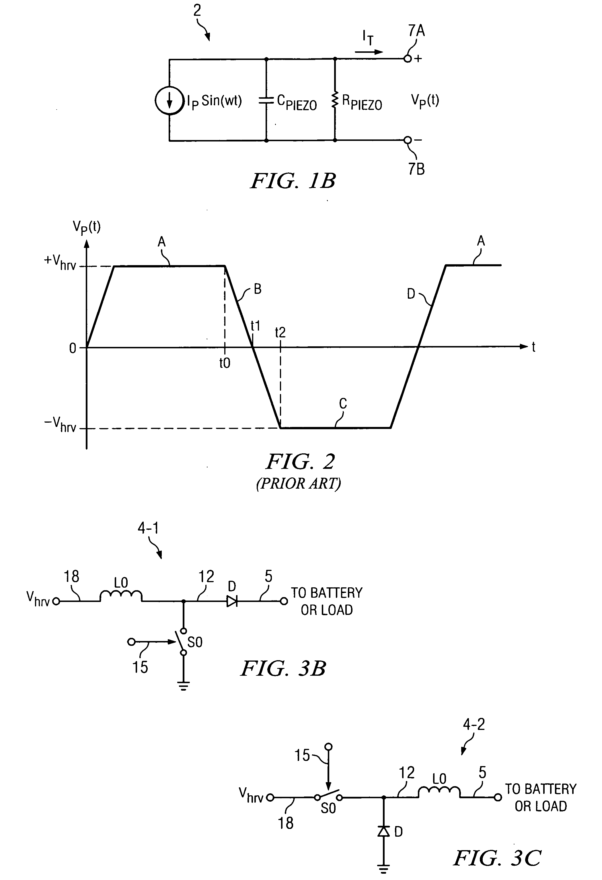
[0030]FIG. 3A shows an energy harvesting system 1-2 that includes conventional piezo-electric harvester 2, active rectifier circuit 3, a comparator 13, an enable logic circuit 17, a switch control and PWM (pulse width modulation) circuit 14, and a DC-DC converter 4 for charging a battery or supercapacitor 6 and / or a load (not shown). As indicated in Prior Art FIG. 1B, piezo harvester 2 can be modeled as a parallel connection of a sinusoidal current source, internal capacitance CPIEZO, and internal resistance RPIEZO. Rectifier circuit 3 includes four switches S1-S4, two comparators A0 and A1, and two inverters 22 and 23. Piezo harvester 2 receives mechanical vibration energy or the like and converts it into a harvested AC voltage VP(t) across piezo harvester 2 and a harvested AC current IPZ(t) in its terminals 7A and 7B. Filtering capacitor C0 can be connected between conductor 18 and ground (i.e., VSS).

[0031]In active rectifier 3, a first terminal of switch S 1 is connected to condu...


PUM


Abstract

A system (1-2) for efficiently transferring harvested vibration energy to a battery (6) includes a piezo harvester (2) generating an AC output voltage (VP(t)) and current (IPZ(t)) and an active rectifier (3) to produce a harvested DC voltage (Vhrv) and current (Ihrv) which charge a capacitance (C0). An enable circuit (17) causes a DC-DC converter (4) to be enabled, thereby discharging the capacitance into the converter, when a comparator (A0,A1) of the rectifier which controls switches (S1-S4) thereof detects a direction reversal of the AC output current (IPZ(t)). Another comparator (13) causes the enable circuit (17) to disable the converter (4) when the DC voltage exceeds a threshold (VREF), thereby causing the capacitance be recharged.

Description

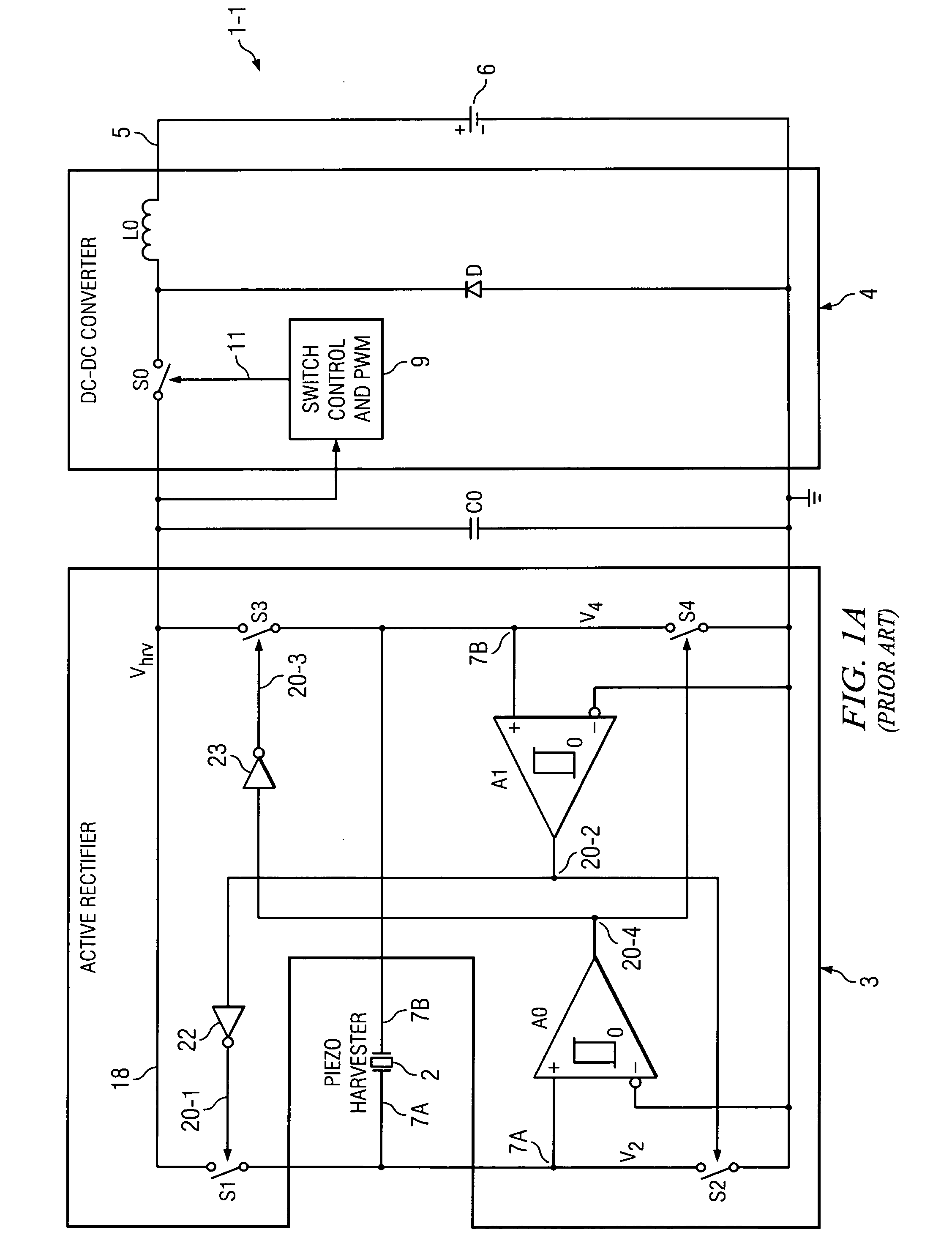
BACKGROUND OF THE INVENTION[0001]The present invention relates generally to efficient transfer of power from a piezo vibration harvester to a DC-DC converter, and more particularly to an improved DC-DC converter circuit for efficiently receiving a maximum amount of power from a piezo harvester.[0002]Recently, various very low power integrated circuits that require extremely low amounts of operating current (often referred to as “nano-power” integrated circuits) have been developed which can be powered by very small amounts of power scavenged or harvested from ambient solar, vibrational, thermal, and / or biological energy sources by means of micro-energy harvesting devices. The harvested power then usually is stored in batteries or supercapacitors. (The term “nano-power” as used herein is intended to encompass circuits and / or circuit components which draw DC current of less than roughly 1 microampere.)[0003]FIG. 1A shows an energy harvesting system 1-1 that includes a conventional pie...

Claims


Application Information

Patent Timeline
IPC IPC(8): H02J7/00
CPCH02M7/219H02M2001/007H02J7/04H02N2/181Y02B70/1408H02M2007/2195H02J7/32H02M7/02H02M1/0067Y02B70/10H02M7/2195H02M1/007
Inventor IVANOV, VADIM V.
Owner TEXAS INSTR INC
Learn More