Liquid crystal display backlight and liquid crystal display device using same

a liquid crystal display and backlight technology, applied in the direction of optics, instruments, optical light guides, etc., can solve the problems of impracticality, uneven brightness, image quality problem of image display devices, etc., and achieve the effect of high reliability and thin construction

Inactive Publication Date: 2011-09-22
PANASONIC CORP
View PDF10 Cites 16 Cited by
  • Summary
  • Abstract
  • Description
  • Claims
  • Application Information

AI Technical Summary

Benefits of technology

[0017]According to the above configuration, a highly reliable liquid crystal display backlight free from a drop in brightness and brightness unevenness due to the deposit of dust on an optical component can be implemented, while maintaining a thin construction.

Problems solved by technology

Because laser light, which has linear propagation characteristics, can be condensed to a small spot, and this becomes a factor of differentiation when the device is downsized, if micro-dust deposits on the surface of the optical component, then an image quality problem occurs to the image display device, such as a drop in transmittance of the laser light and uneven brightness.
However these solution are impractical when the necessity of an efficient cooling system for suppressing a temperature rise of the LCD backlight, including the optical system, and the manufacturing cost of the liquid crystal display device are considered.

Method used


Image

  • Liquid crystal display backlight and liquid crystal display device using same
  • Liquid crystal display backlight and liquid crystal display device using same
  • Liquid crystal display backlight and liquid crystal display device using same

Examples


embodiment 1

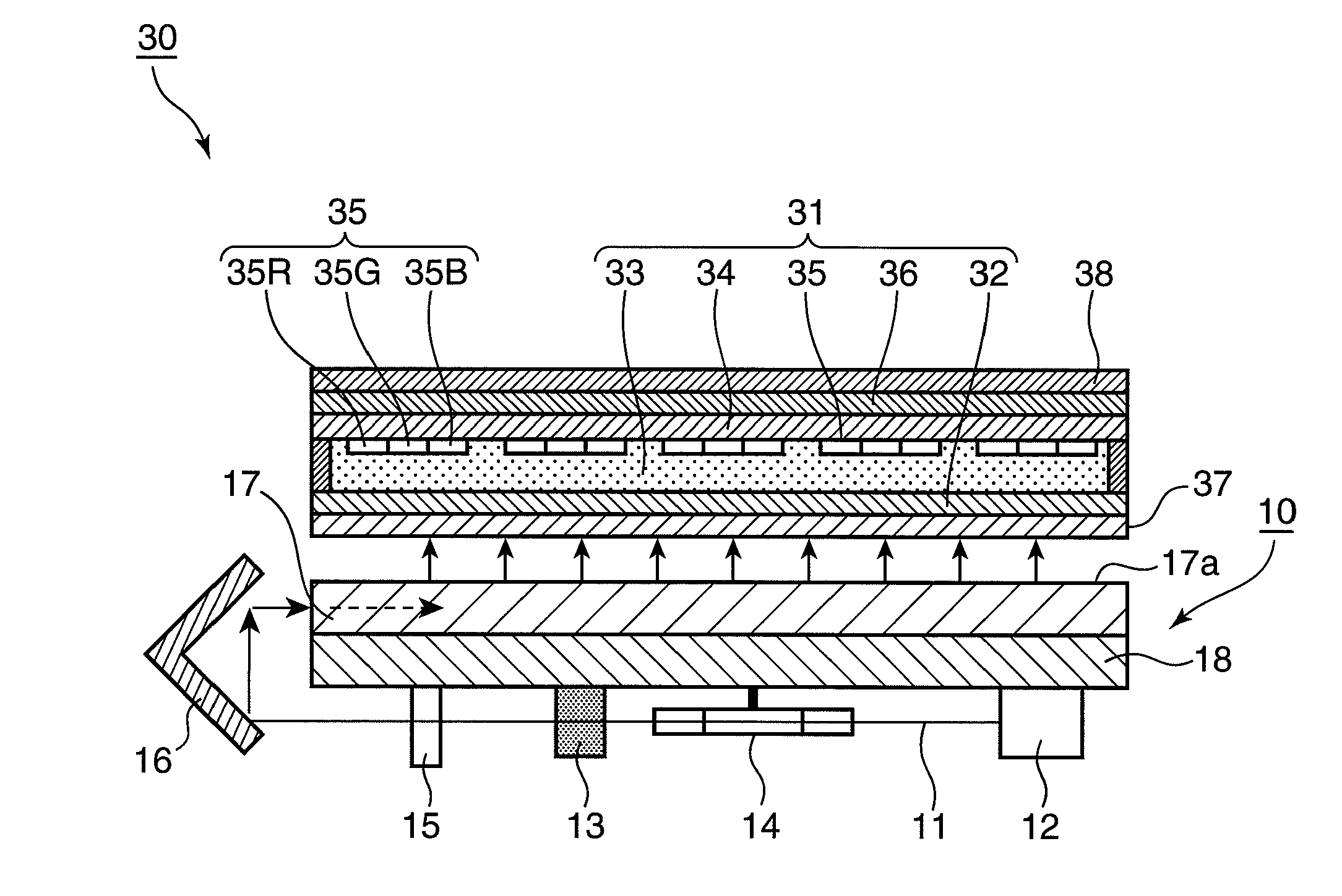
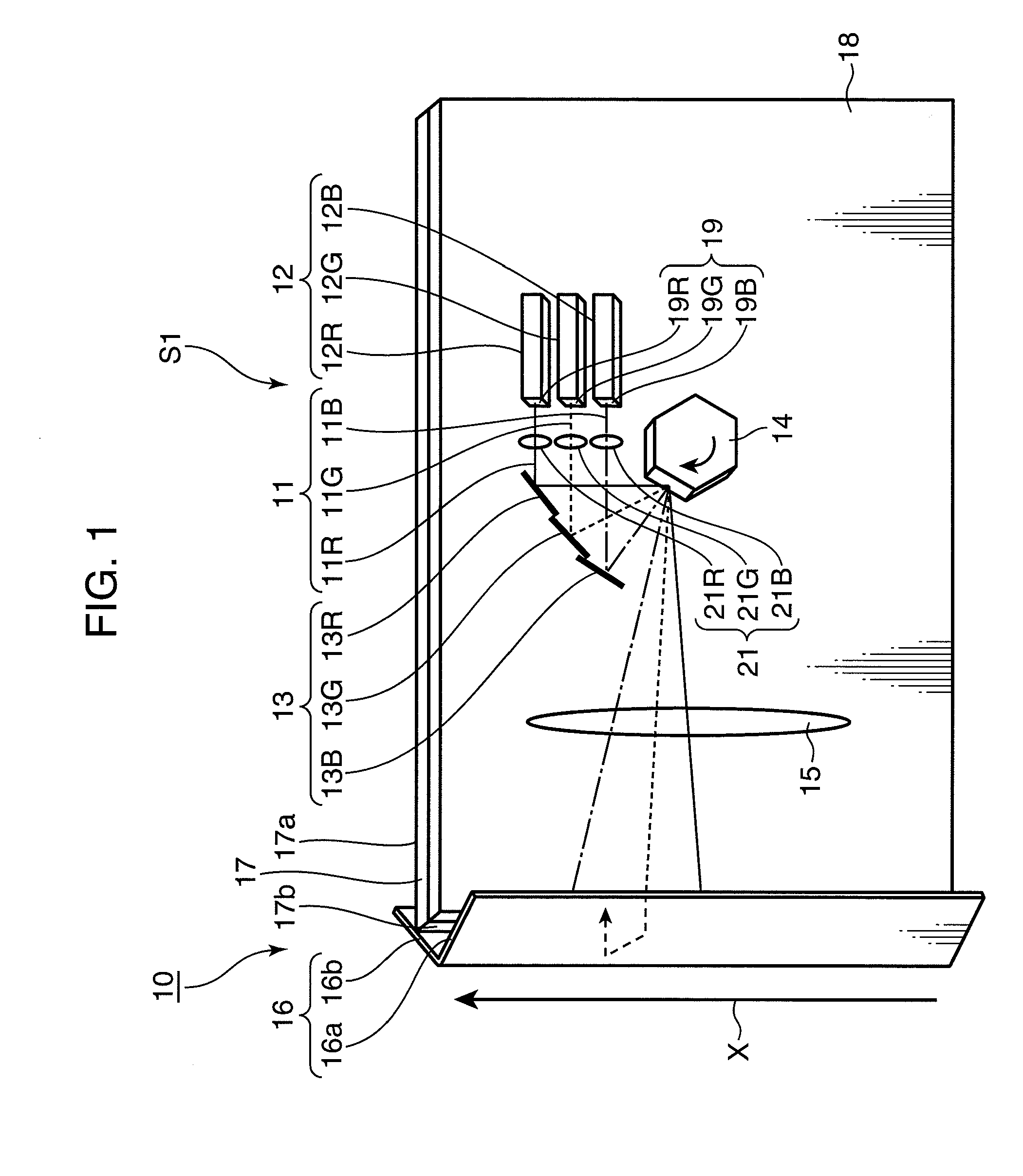
[0043]FIG. 1 is a diagram depicting a general configuration of an LCD backlight 10 according to Embodiment 1 of the present invention. This LCD backlight 10 has a plurality of light source 12 (red light source 12R, green light source 12G and blue light source 12B) that emit a plurality of laser lights 11 (red laser light 11R, green laser light 11G and blue laser light 11B), a plurality of lenses 21 (red laser light lens 21R, green laser light lens 21G and blue laser light lens 21B), a plurality of mirrors 13 (red laser light reflection mirror 13R, green laser light reflection mirror 13G and blue laser light reflection mirror 13B), a rotary polygon mirror 14, scanning lens 15, return mirror 16 (front side return mirror 16a and rear side return mirror 16b), light guiding plate 17, and optical board 18 that supports each optical component.

[0044]In the LCD backlight 10 of Embodiment 1, a transforming optical system is constituted by the lenses 21, mirrors 13, rotary polygon mirror 14, s...

embodiment 2

[0075]FIG. 11 is a perspective view depicting a general configuration of an LCD backlight 40 according to Embodiment 2 of the present invention, and FIG. 12 is a diagram depicting a general configuration around the light source of the LCD backlight shown in FIG. 11. This LCD backlight 40 has a configuration similar to the LCD backlight 10 according to Embodiment 1, but a difference from Embodiment 1 is that a light source unit 42, which is disposed separately from the rear face portion of the light guiding plate 17, a fiber (optical fiber) 49, an emission end portion 41 of the fiber 49 and a fiber collimator 43, are equipped as the composing elements. Another difference from Embodiment 1 is that the light source unit 42 has a blue laser light reflection mirror 45, red laser light reflection mirror 48 and dichroic mirrors 46 and 47, in addition to the plurality of light sources 12 (red light source 12R, green light source 12G and blue light source 12B), and the laser light that is em...

embodiment 3

[0083]FIG. 13 is a diagram depicting a general configuration of an LCD backlight 70 according to Embodiment 3 of the present invention. This LCD backlight 70 has a configuration similar to the LCD backlight 40 according to Embodiment 2, but a difference is that a multi-light source 71, that is a plurality of lasers housed in an enclosure, is used for the light source, and the rest of the configuration is the same as the LCD backlight 40 of Embodiment 2.

[0084]The multi-laser light 73 emitted from the multi-light source 71 is transformed into substantially parallel light by the collimator 72, is then returned by the mirror 13, and deflected and scanned by the rotary polygon mirror 14. The multi-laser light 73 reflected by the rotary polygon mirror 14 is scanned in the X direction, and enters the light guiding plate 17 via the scanning lens 15 and return mirror 16. If this multi-light source 71 is a light source housing the red, blue and green semiconductor laser, for example, the mult...


PUM

PropertyMeasurementUnit
sizeaaaaaaaaaa
thicknessaaaaaaaaaa
light transmissionaaaaaaaaaa

Abstract

An LCD backlight (10) has a light source (12) that emits a laser light, a lens (21), a mirror (13), a rotary polygon mirror (14), a scanning lens (15) and a return mirror (16) constituting a transforming optical system that transforms the laser light from the light source (12) to a linear light, and a light guiding plate (17) that allows the linear light to enter and emits two-dimensional light in the horizontal direction. An emission end face (19) of the light source (12) is disposed in a rear face side of the light guiding plate (17) so that a surface normal line thereof is in the horizontal direction or is inclined downward from the horizontal direction, and the lens (21), mirror (13) and scanning lens (15) are disposed in the rear face side of the light guiding plate (17), so that surface normal lines of the light transmission surface and light reflection surface thereof are all in the horizontal direction or are inclined downward from the horizontal direction.

Description

TECHNICAL FIELD[0001]The present invention relates to a thin and high brightness LCD (liquid crystal display) backlight used for a non-self emission type display device such as a liquid crystal TV, and a liquid crystal display device using this LCD backlight.BACKGROUND ART[0002]A liquid crystal display uses a system of displaying images by controlling the transmission quantity of light that is irradiated from the rear face using the electro-optical effect based on liquid crystal molecule orientation, and generally requires a flat illumination device called a “backlight unit” that is constituted by fluorescent display tubes. Recently the screen size of liquid crystal devices is increasing, and now even a 50 inch size or larger TV display device is commercialized. At the same time power consumption is increasing as well as screen size increases, therefore technical developments to implement lower power consumption is demanded, and in order to minimize the space to be occupied in a roo...

Claims


Application Information

Patent Timeline
Patent Type & Authority Applications(United States)
IPC IPC(8): G02F1/1335
CPCG02B6/0031G02B6/0068G02B6/0066
Inventor SHIKII, SHINICHIKADOWAKI, SHINICHIITOH, TATSUONAGATA, TAKAYUKIYAMAMOTO, KAZUHISA
Owner PANASONIC CORP
Why Eureka
Try Eureka