
Transmission apparatus, reception apparatus and communication system

a technology of reception apparatus and transmission apparatus, applied in the field of transmission apparatus, reception apparatus and communication system, can solve problems such as errors in s/sub>a /sub>decoding, and achieve the effects of increasing user throughput, good transmission, and good transmission

Active Publication Date: 2011-09-22
SHARP KK
View PDF5 Cites 11 Cited by
  • Summary
  • Abstract
  • Description
  • Claims
  • Application Information

AI Technical Summary

Benefits of technology

[0009]The present invention has been made in view of such circumstances, and has an object to provide a transmission apparatus, a reception apparatus and a communication system which can improve the error rate by obtaining the transmission antenna diversity effect even when the channel state of one antenna is poor.
[0011]Since the spectrum output from the precoding part is divided and the divided spectrums are transmitted from different antennas respectively as described above, MIMO communication having a transmission antenna diversity gain becomes possible. This transmission antenna diversity effect enables good transmission, thereby increasing the user throughput.
[0013]With such configuration, the number of divided spectrums can be changed according to the number of code words. As a result, MIMO communication having the transmission antenna diversity gain becomes possible. This transmission antenna diversity effect enables good transmission, thereby increasing the user throughput.
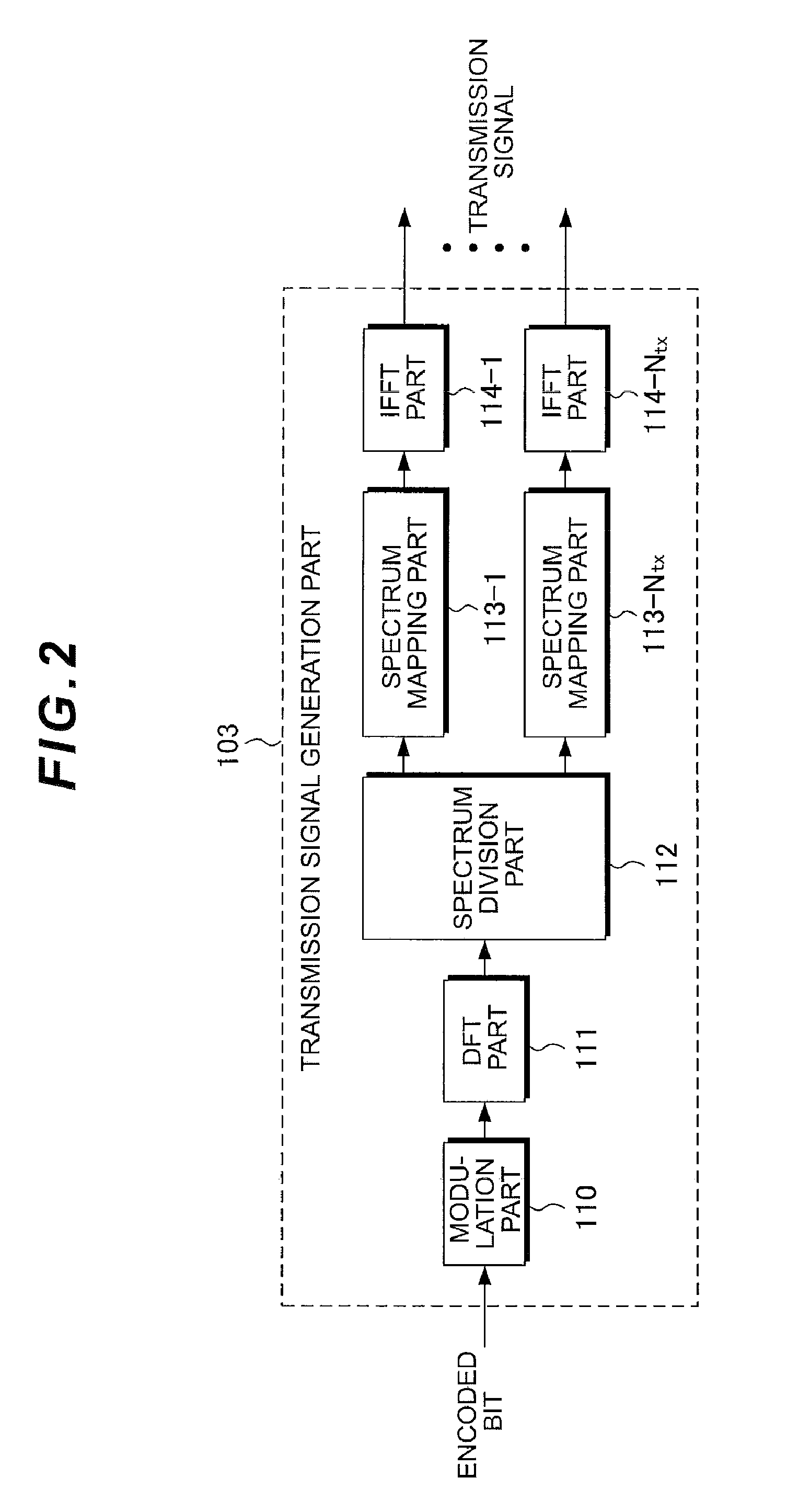
[0016]As described above, by performing DFT (Discrete Fourier Transform) to convert the time domain signal into the frequency domain signal, it is possible to perform precoding and then, spectrum division.
[0022]With such configuration, MIMO communication having the transmission antenna diversity gain becomes possible. This transmission antenna diversity effect enables good transmission, thereby increasing a user throughput.
[0023]According to the present invention, by dividing the spectrum of the single carrier and transmitting multiplexed spectrums from the antennas, MIMO communication having the transmission antenna diversity gain becomes possible. This transmission antenna diversity effect enables good transmission, thereby increasing the user throughput.

Problems solved by technology

Although SA may be correctly decoded at error correction decoding due to the existence of SB received with high likelihood, when the coding rate is high, SA is decoded with error.

Method used


Image

  • Transmission apparatus, reception apparatus and communication system
  • Transmission apparatus, reception apparatus and communication system
  • Transmission apparatus, reception apparatus and communication system

Examples


first embodiment

[0085]In First embodiment, efficient transmission method and reception method in single carrier SU-MIMO will be described. In this description, single carrier transmission is defined as a transmission system to generate a signal in a time domain. Accordingly, although First embodiment will be described using DFT-S-OFDM as an example, the present invention can be also applied to a single carrier-based transmission system such as Clustered DFT-S-OFDM.

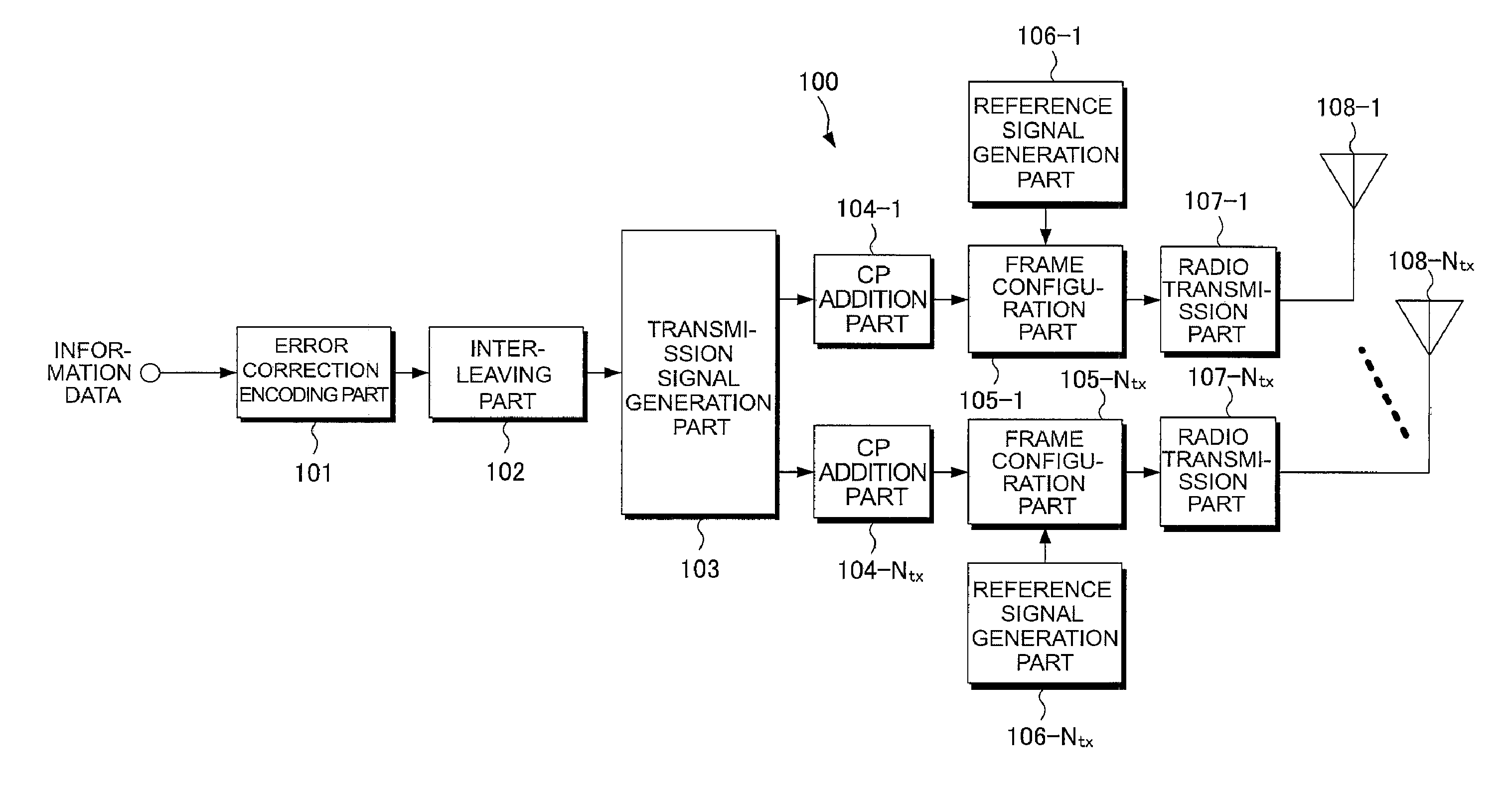
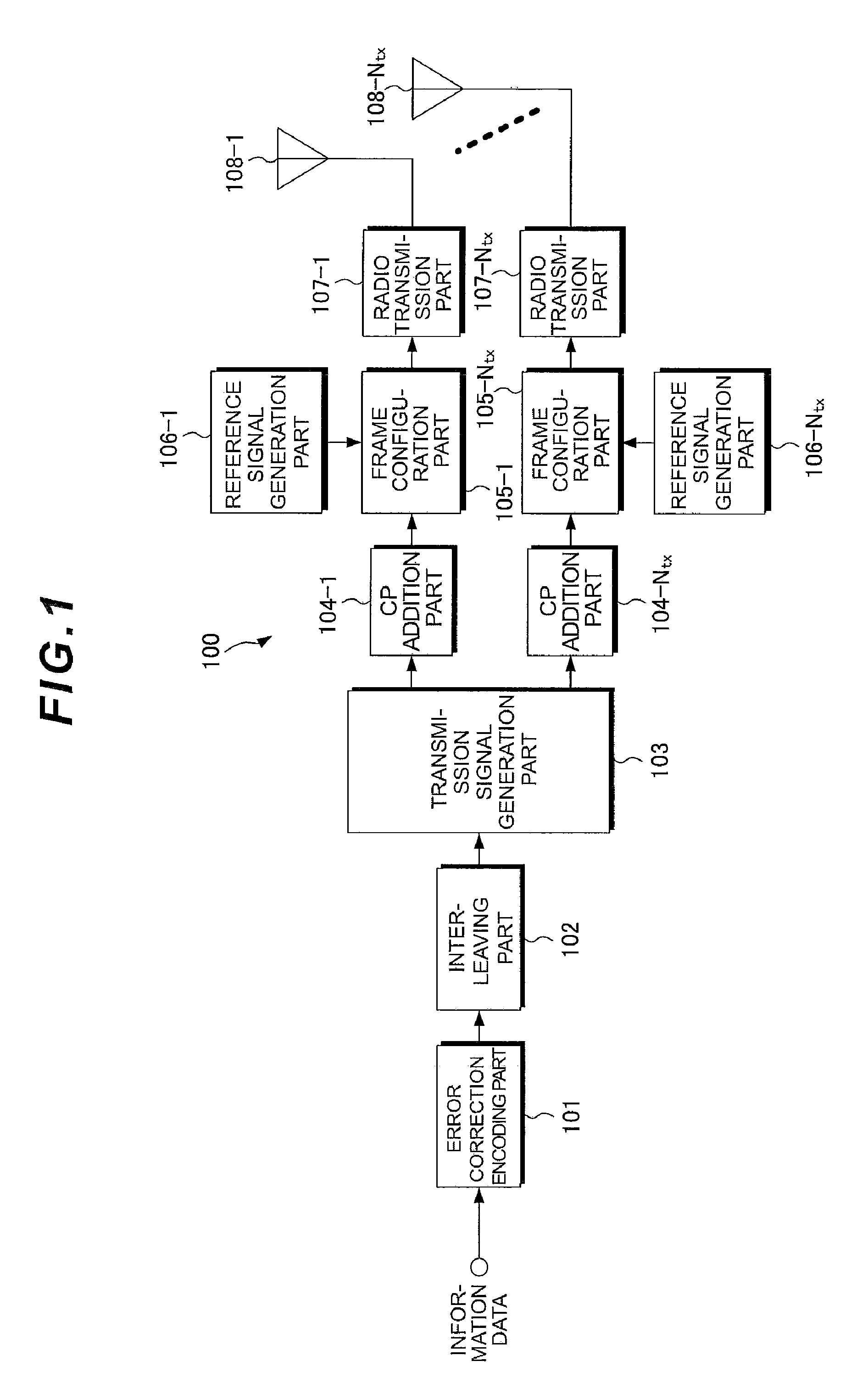
[0086]FIG. 1 is a diagram showing schematic configuration of a transmitter in accordance with First embodiment. This transmitter 100 is assumed to include Ntx transmission antennas and perform single carrier transmission. In the transmitter 100, an information data sequence is input to an error correction coding part 101. The error correction coding part 101 performs error correction coding such as a convolutional code, a turbo code or an LDPC (Low Density Parity Check) code, on the input data bit sequence and outputs an obtained encoded ...

second embodiment

[0105]First embodiment shows the case where the number of error correction coding parts is one. However, in a downlink in LTE, the transmitter includes a plurality of error correction coding parts to generate a plurality of code words. The coding parts are provided in order to perform MIMO separation by SIC (Successive Interference Cancellation) in the receiver and to decrease excessive retransmission by requesting retransmission for each code word.

[0106]FIG. 7 is a diagram showing a part of a transmitter standardized in LTE. In FIG. 7, the description is provided assuming that the number of code words is n and the number of transmission antennas is m. Scrambling parts 70-1 to 70-n scramble transmission data by using known signals. Modulation parts 71-1 to 71-n modulate signals input from the scrambling parts 70-1 to 70-n by QPSK (Quaternary Phase Shift Keying), 16 QAM (Quadrature Amplitude Modulation) or the like. When the number of layers is larger than the number of code words, a...

third embodiment

[0113]In Third embodiment, efficient transmission method and reception method to determine the number of used frequency bands according to the number of code words will be described. In this specification, the code word is defined as the number of blocks included in one transmission event and subjected independently to error correction coding. Single carrier transmission is defined as a transmission system to generate a signal in the time domain. A specific example of the case where the number of code words is made equal to the number of used frequency bands so that there is a one-to-one correspondence between the code word and the used frequency band will be described below.

[0114]FIG. 13 is a diagram showing configuration of a transmitter in accordance with Third embodiment. Here, it is assumed that the number of code words is p. In a transmitter 130, information data sequences for the number of code words are input to CRC addition parts 131-1 to 131-p, respectively. The CRC additi...


PUM


Abstract

In SU-MIMO, even when the channel state of one antenna is poor, an error ratio is improved by obtaining a transmission antenna diversity effect. A transmission apparatus 100 that has a plurality of antennas 108-1 to 108-Ntx and transmits a signal according to a MIMO (Multiple Input Multiple Output) system includes a DFT part 111 for precoding transmission data and a spectrum division part 112 for dividing a spectrum output from the DFT part 111. The divided spectrums are transmitted from the different antennas 108-1 to 108-Ntx, respectively.

Description

TECHNICAL FIELD[0001]The present invention relates to a technology of transmitting / receiving a signal by use of a plurality of antennas according to a MIMO (Multiple Input Multiple Output) system.BACKGROUND ART[0002]In mobile communication, high-speed data transmission has been demanded heretofore. In a 3GPP (3rd Generation Partnership Project), LTE (Long Term Evolution) has been increasingly standardized as a standard that enables high-speed transmission and its specifications are being completed. In an uplink in LTE, DFT-S-OFDM (“Discrete Fourier Transform Spread Orthogonal Frequency Division Multiplexing”, which is also referred to as “SC-FDMA”) is adopted. Because DFT-S-OFDM can multiplex a frequency spectrum of each user in a frequency domain without using a guard band, the spectral efficiency is considered to be high.[0003]More recently, LTE-Advanced (LTE-A) as an enhancement of LTE has been standardized as a 4th generation mobile communication system. LTE-A needs to support a...

Claims


Application Information

Patent Timeline
Patent Type & Authority Applications(United States)
IPC IPC(8): H04L27/28H04B1/69
CPCH04B7/0615H04J11/004H04B7/0854
Inventor NAKAMURA, OSAMUHAMAGUCHI, YASUHIROYOKOMAKURA, KAZUNARIGOTO, JUNGOTAKAHASHI, HIROKI
Owner SHARP KK
Learn More