Heat dissipation housing for led lamp

a technology for led lamps and housings, which is applied in the field of housing for led lamps, can solve the problems of increasing the burden on the natural environment, reducing and reducing the use life of incandescent lamps, so as to improve the efficiency of air convection. efficiency, the effect of increasing the heat dissipation surfa

Inactive Publication Date: 2011-09-29
SKYNET ELECTRONICS
View PDF4 Cites 10 Cited by
  • Summary
  • Abstract
  • Description
  • Claims
  • Application Information

AI Technical Summary

Benefits of technology

A primary object of the present invention is to provide a heat dissipation housing for an LED lamp, which is made as a one-piece member by metal casting, and formed with a receiving channel axially passing therethrough for receiving a power printed circuit board (PCB) and wires of the LED lamp. An outer surface of the heat dissipation housing is axially formed with a plurality of cooling fins. Each of the cooling fins is radially extended out of the heat dissipation housing, while the radial length of each of the cooling fins adjacent to a first end of the heat dissipation housing is smaller than that of each of the cooling fins adjacent to a second end of the heat dissipation housing. The first end of the heat dissipation housing is used to carry an electrode cap, while the second end thereof is used to carry a light emitting element of the LED lamp (such as a base with LED). Each of the cooling fins has two opposite sides, and an included angle is defined between the two opposite sides to prevent from forming a dead space of air convection between the adjacent cooling fins, so as to substantially enhancing the efficiency of air convection between the cooling fins. Each of the cooling fins is formed with a plurality of heat dissipation holes therein for communicating the air inside and outside the heat dissipation housing, wherein the heat dissipation holes can substantially increase the heat dissipation surface of each of the cooling fins, and a heat exchange between heat in each of the cooling fins and a cooling air outside each of the cooling fins can be carried out through the heat dissipation holes. Therefore, when the light emitting element is installed on a second end of the heat dissipation housing and starts to emit color light, heat exchange between heat generated by the light emitting element and the ambient cooling air outside the heat dissipation housing can be carried out through the cooling fins on the heat dissipation housing and the heat dissipation holes by both of thermal conduction and thermal convection. Meanwhile, the space between the cooling fins can provide the better air convection efficiency for rapidly dissipating heat on the surface of the cooling fins and heat in the heat dissipation holes to the ambient atmosphere. As a result, the temperature of the light emitting element can be rapidly lowered to a better operational temperature, so as to efficiently enhance the light emitting quality, the light emitting efficiency and the usage life of the light emitting element.
A secondary object of the present invention is to provide a heat dissipation housing for an LED lamp, wherein each portion of an inner surface of the heat dissipation housing corresponding to each of the cooling fins is formed with a recess along an axial direction of the heat dissipation housing, while the radial depth of each of the recesses adjacent to the first end of the heat dissipation housing is smaller than that of each of the recesses adjacent to the second end of the heat dissipation housing, wherein the recess is communicated with the heat dissipation holes. Therefore, the inner heat dissipation surface of each of the cooling fins can be substantially increased, so that heat generated by the LED on the second end of the heat dissipation housing can be rapidly transmitted to an outer surface of the cooling fins through the considerable heat dissipation surface provided by the recesses for carrying out a faster heat conduction effect. On the other hand, because each of the recesses is further formed with a larger heat convection space in the heat dissipation housing and each of the recesses is communicated with the receiving channel and the heat dissipation holes, the cooling air outside each of the cooling fins can easily enter each of the recesses and the receiving channel through the heat dissipation holes, while heat air inside the recesses and the receiving channel also can be smoothly dissipated out of the heat dissipation housing through the heat dissipation holes, for the purpose of carrying out a faster heat convection effect.

Problems solved by technology

However, the usage life of the incandescent lamps is relatively short (the average usage life there is only 1,000 hours).
However, the incandescent lamp only can convert about 10% of received electric energy into light energy, while about 90% of electric energy is converted into useless heat energy which is then dissipated into the ambient atmosphere.
As a result, not only the electric energy is considerably wasted and consumed, but also the burden of the natural environment is heavier.
However, the fluorescent lamp is filled with harmful mercury vapor and phosphorus-based fluorescent paints, while the usage life of the fluorescent lamp is still relatively short (only 6,000 hours).
In a case of frequently using a large number of fluorescent lamps, there will be many waste fluorescent lamps in a short time.
Once the waste fluorescent lamps are casually discarded, the harmful mercury vapor and phosphorus-based fluorescent paints therein will be released to pollute the natural environment and harm the ecology.
As described above, although the LED lamp becomes the mainstream of illumination lamps nowadays, LEDs still generate considerable heat while emitting light.
Meanwhile, the higher the brightness of the LED is, the more waste heat the LED generates.
If the LED lamp is continuously long-term used, it will cause serious material aging and luminous decay phenomenon, resulting in seriously shortening the usage life of the LED lamp.
As a result, the temperature difference between the cooling fins 102 and the ambient atmosphere is gradually narrowed, resulting in lowering the efficiency of air convection between the adjacent cooling fins 102.
If heat transmitted from the LED 131 can not be efficiently dissipated, the operational temperature of the LED 131 can not be lowered, so that there is still problems of material aging and luminous decay phenomenon existing in the light emitting module 13 installed on the heat dissipation housing 10 to seriously shortening the usage life of the LED lamp.

Method used


Image

  • Heat dissipation housing for led lamp
  • Heat dissipation housing for led lamp
  • Heat dissipation housing for led lamp

Examples


Embodiment Construction

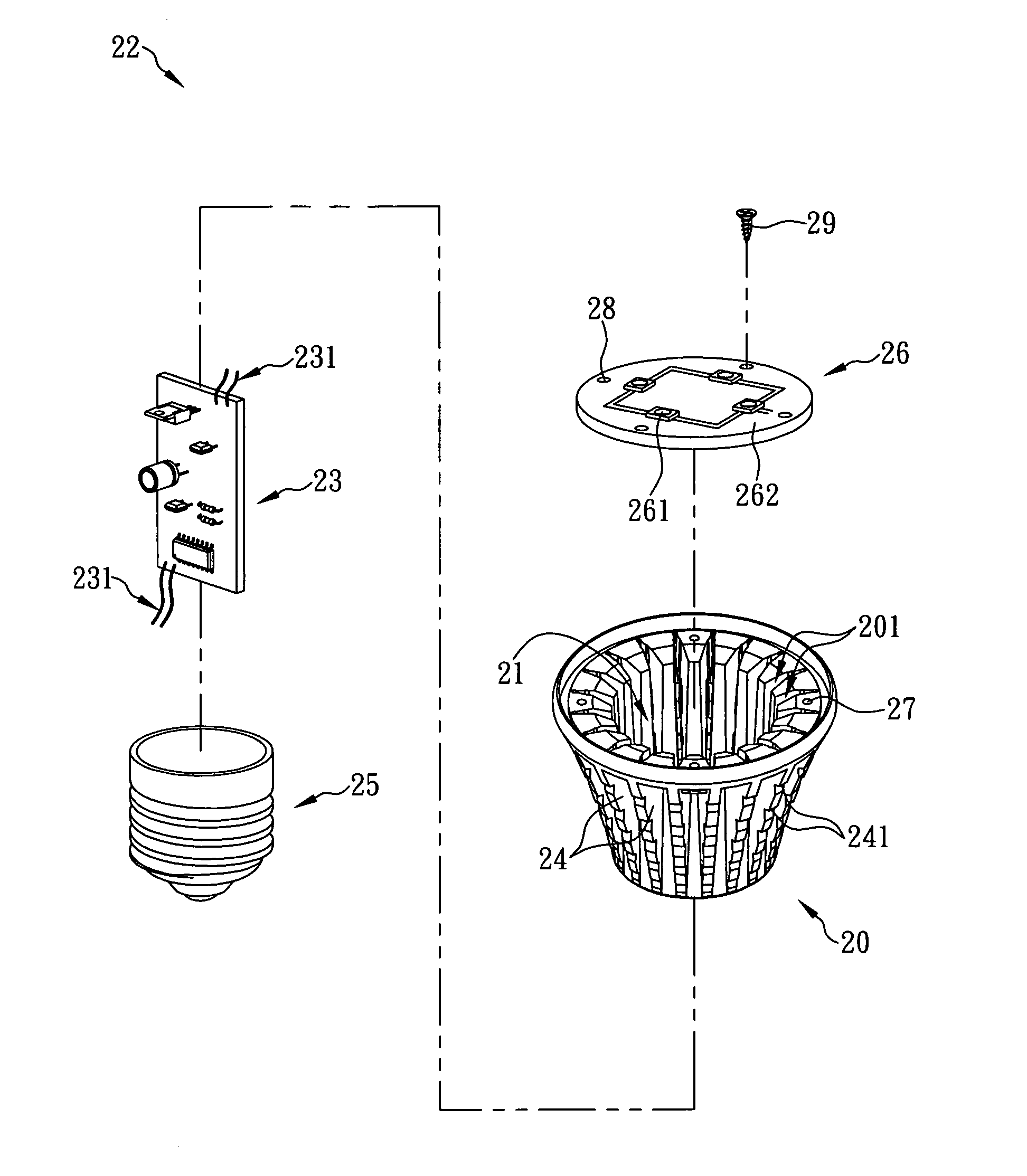
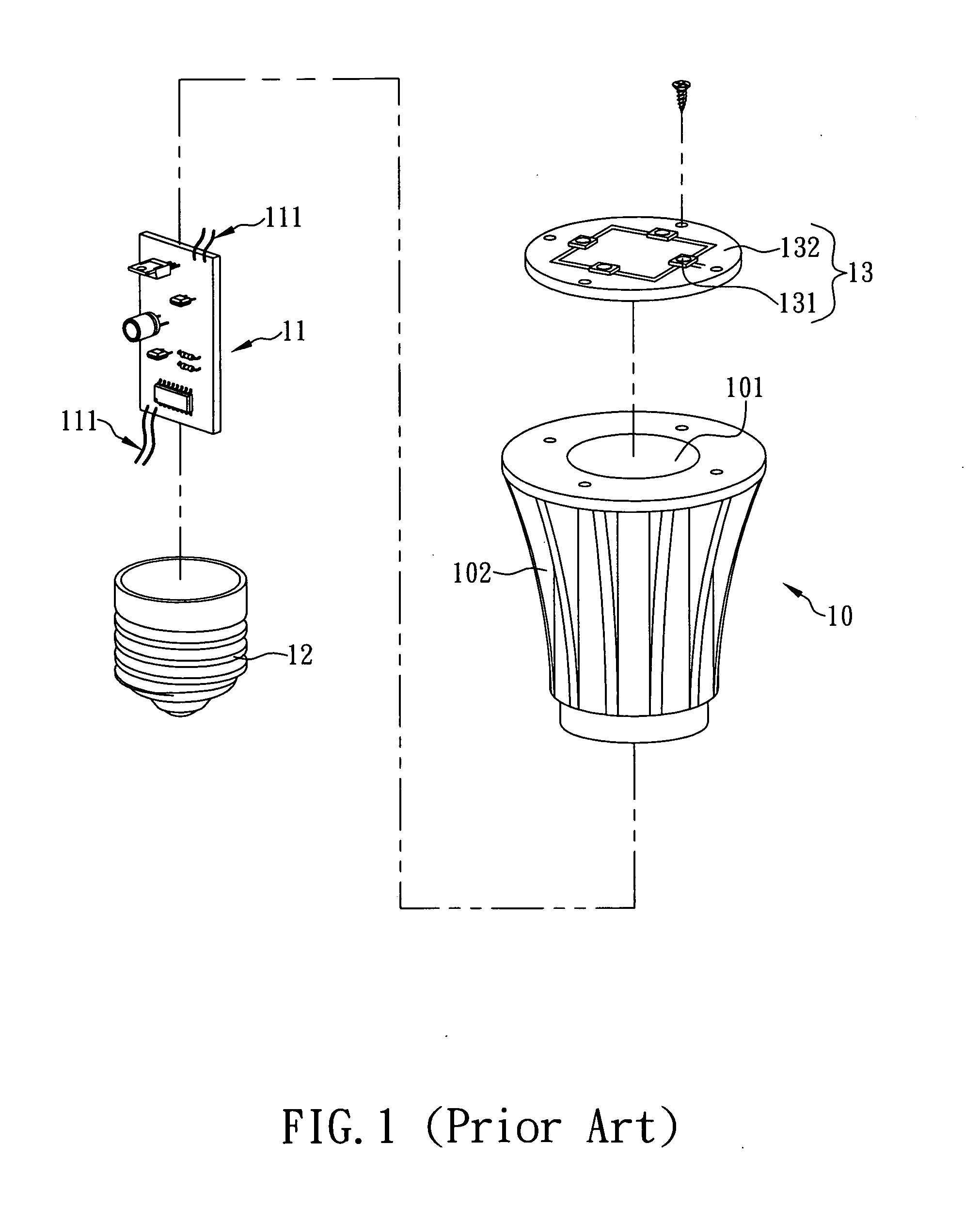
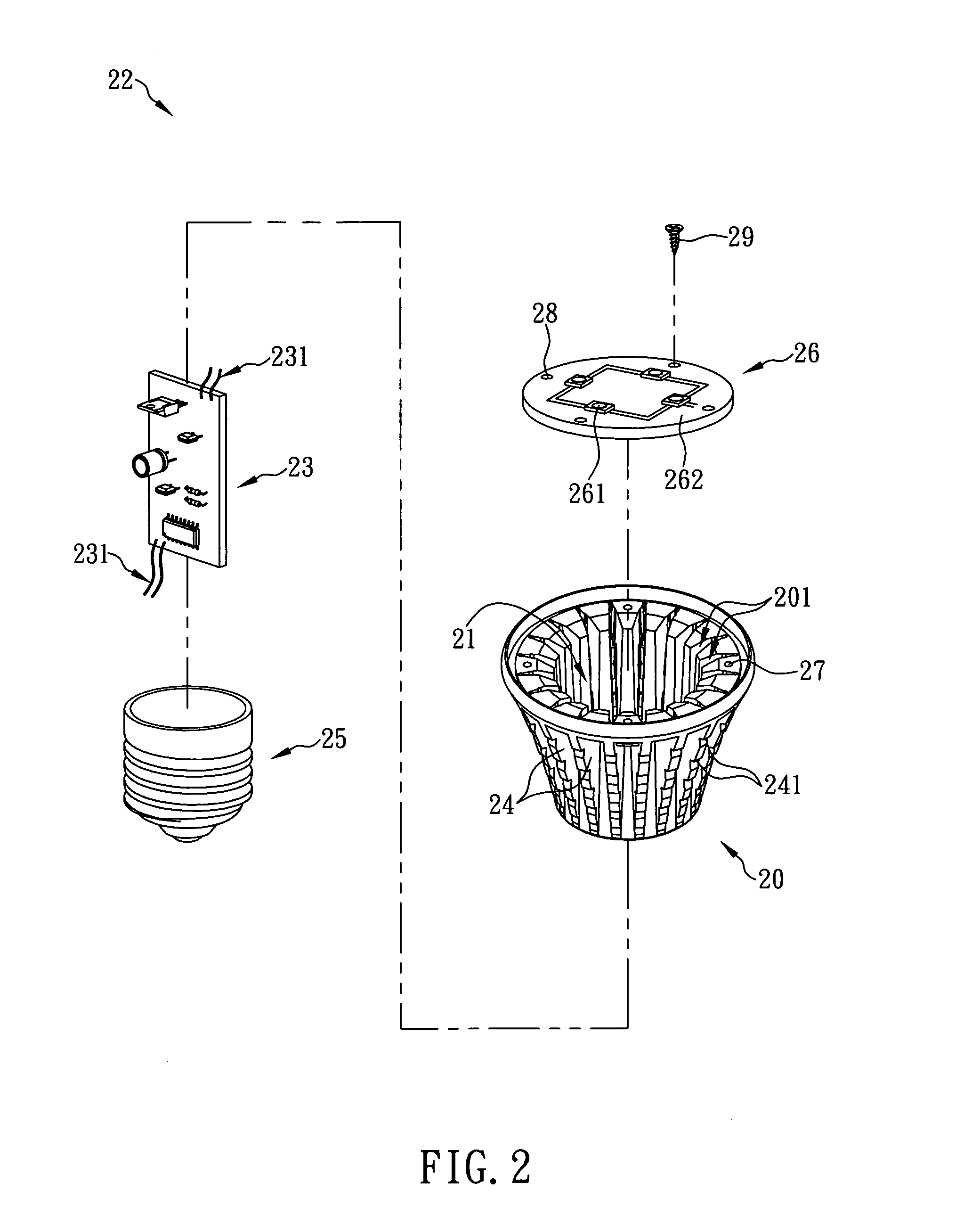
Generally, while a light emitting diode (LED) emits color light, the LED generates a large amount of heat. Thus, an LED lamp installed with LEDs is generally provided with a heat dissipation housing to dissipate heat generated by the LEDs to the ambient environment. Typically, the manufacturing methods of the heat dissipation housing can be classified into metal extrusion and metal casting. For a heat dissipation housing manufactured by metal extrusion, a pure metal plate (such as an aluminum plate) is extruded to integrate into one piece, so as to form the heat dissipation housing. However, the heat dissipation housing manufactured by metal extrusion has a rougher surface, so that the rougher surface must be finished by a secondary processing. It causes that the processing procedures are complicated and cost more time and manpower of manufacturers, so that the manufacture cost of the heat dissipation housing will be increased and the market competitiveness of the manufacturers will...


PUM


Abstract

The present invention is to provide a heat dissipation housing for an LED lamp, which is made as a one-piece member by metal casting and formed with a receiving channel axially passing therethrough. A plurality of cooling fins axially are formed on an outer surface of the housing, wherein each said cooling fin is radially extended out of the housing and formed therein with a plurality of heat dissipation holes, and has two opposite sides with an included angle defined therebetween. Therefore, when an LED lamp installed on an end of the receiving channel starts to emit light, heat exchange between the LED lamp and the ambient cooling air outside the housing can be carried out through the cooling fins and the heat dissipation holes by both of thermal conduction and thermal convection, so as to effectively enhance the heat dissipation efficiency of the housing for the LED lamp.

Description

FIELD OF THE INVENTIONThe present invention relates to a housing for an LED lamp, more particularly to a heat dissipation housing for an LED lamp, of which an outer surface is axially formed with a plurality of cooling fins. Each of the cooling fins is radially extended out of the heat dissipation housing and formed with a plurality of heat dissipation holes therein for communicating the air inside and outside the heat dissipation housing, wherein each of the cooling fins has two opposite sides, and an included angle is defined between the two opposite sides. Thus, when an LED lamp is installed on the heat dissipation housing and starts to emit light, heat exchange between heat generated by the LED lamp and the ambient cooling air outside the heat dissipation housing can be carried out through the cooling fins and the heat dissipation holes by both of thermal conduction and thermal convection, so as to effectively enhance the heat dissipation efficiency of the housing for the LED la...

Claims


Application Information

Patent Timeline
Patent Type & Authority Applications(United States)
IPC IPC(8): F28F7/00
CPCF21K9/1355F21V29/773F21V29/507F21Y2101/02F21K9/23F21Y2115/10
Inventor LIANG, JIM-HUNG
Owner SKYNET ELECTRONICS
Why Eureka
Try Eureka