Imprint apparatus and method of manufacturing article

a technology of imprinting apparatus and manufacturing article, which is applied in the field of imprinting apparatus, can solve the problems of defect in the pattern transfer onto the substrate, long time to fill, etc., and achieve the effect of suppressing the complication of the arrangement of the imprinting apparatus and improving the throughput and/or yield of imprint processing

Active Publication Date: 2011-09-29
CANON KK
View PDF3 Cites 9 Cited by
  • Summary
  • Abstract
  • Description
  • Claims
  • Application Information

AI Technical Summary

Benefits of technology

[0006]The present invention provides an advantageous technique to improve the throughput and / or yield of imprint processing while suppressing complication of the arrangement of an imprint apparatus.

Problems solved by technology

The conventional imprint methods pose problems in that it takes a long time to fill concave portions of the pattern formed on the mold with the resin, and that a defect occurs if a curing process is executed before the concave portions of the pattern are completely filled with the resin.
The conventional imprint methods also pose the problems that a large force is necessary to separate the mold from the resin or the substrate after the resin cures, and that this leads to a defect in the pattern transferred onto the substrate.

Method used


Image

  • Imprint apparatus and method of manufacturing article
  • Imprint apparatus and method of manufacturing article
  • Imprint apparatus and method of manufacturing article

Examples


first embodiment

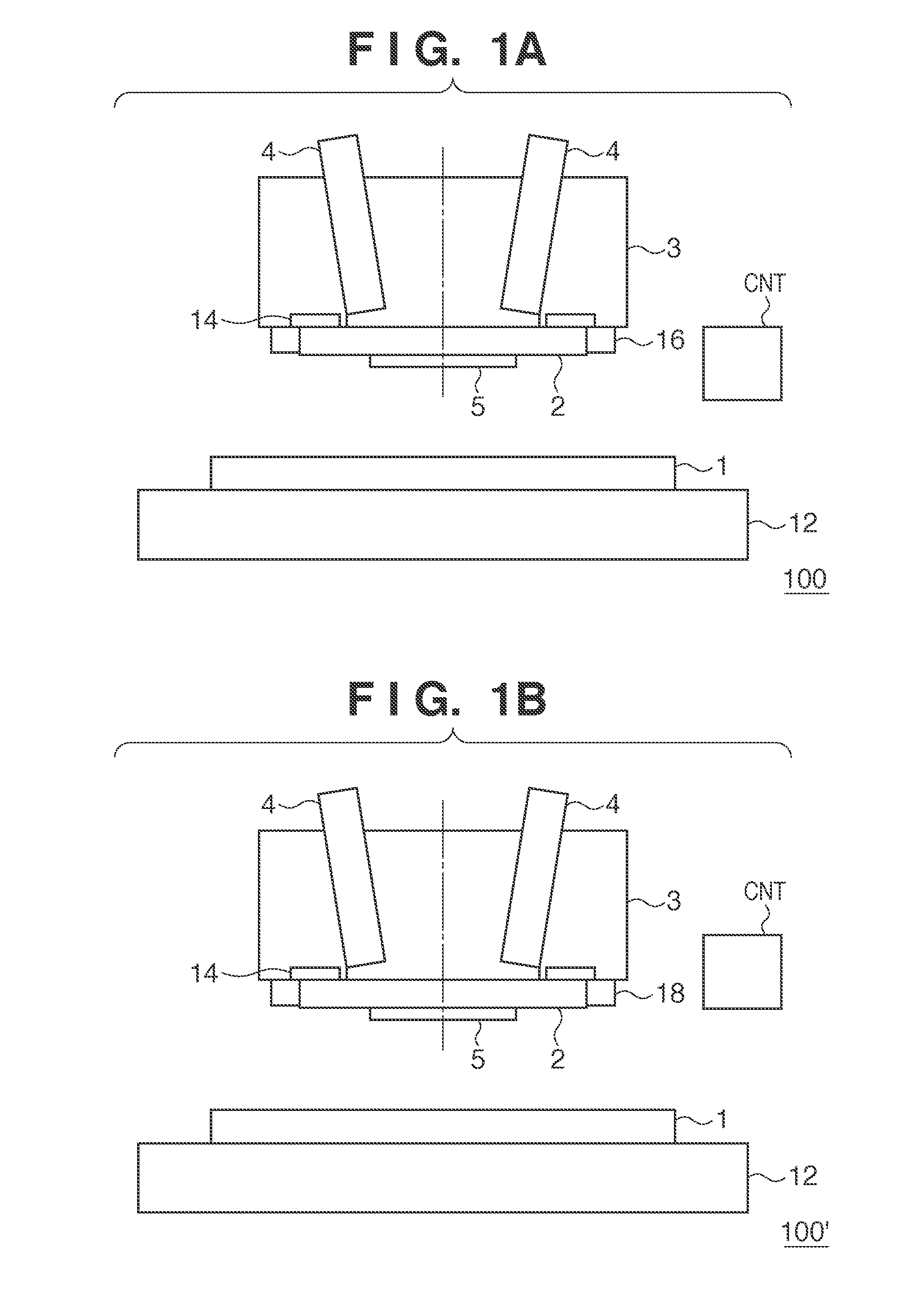
[0016]An imprint apparatus 100 according to the first embodiment of the present invention will be described with reference to FIG. 1A. The imprint apparatus 100 supplies energy to a resin dispensed on a substrate 1 such as a wafer or a glass substrate while a pattern surface PS of a mold 2 is in contact with the resin, thereby curing the resin. Thus, a pattern formed on the pattern surface PS of the mold 2 is transferred onto the substrate 1 as the pattern of the resin. The energy used to cure the resin is typically light (for example, ultraviolet light) or heat. The imprint apparatus 100 can include, for example, a positioning mechanism 12 which positions the substrate 1, and an imprint head 3 having a chuck 14 which holds the mold 2. The imprint apparatus 100 can additionally include a controller CNT which controls an imprint operation, a driving mechanism (not shown) which brings the mold 2 into contact with the substrate 1 via the resin or separates the mold 2 from the substrate...

second embodiment

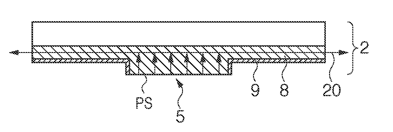
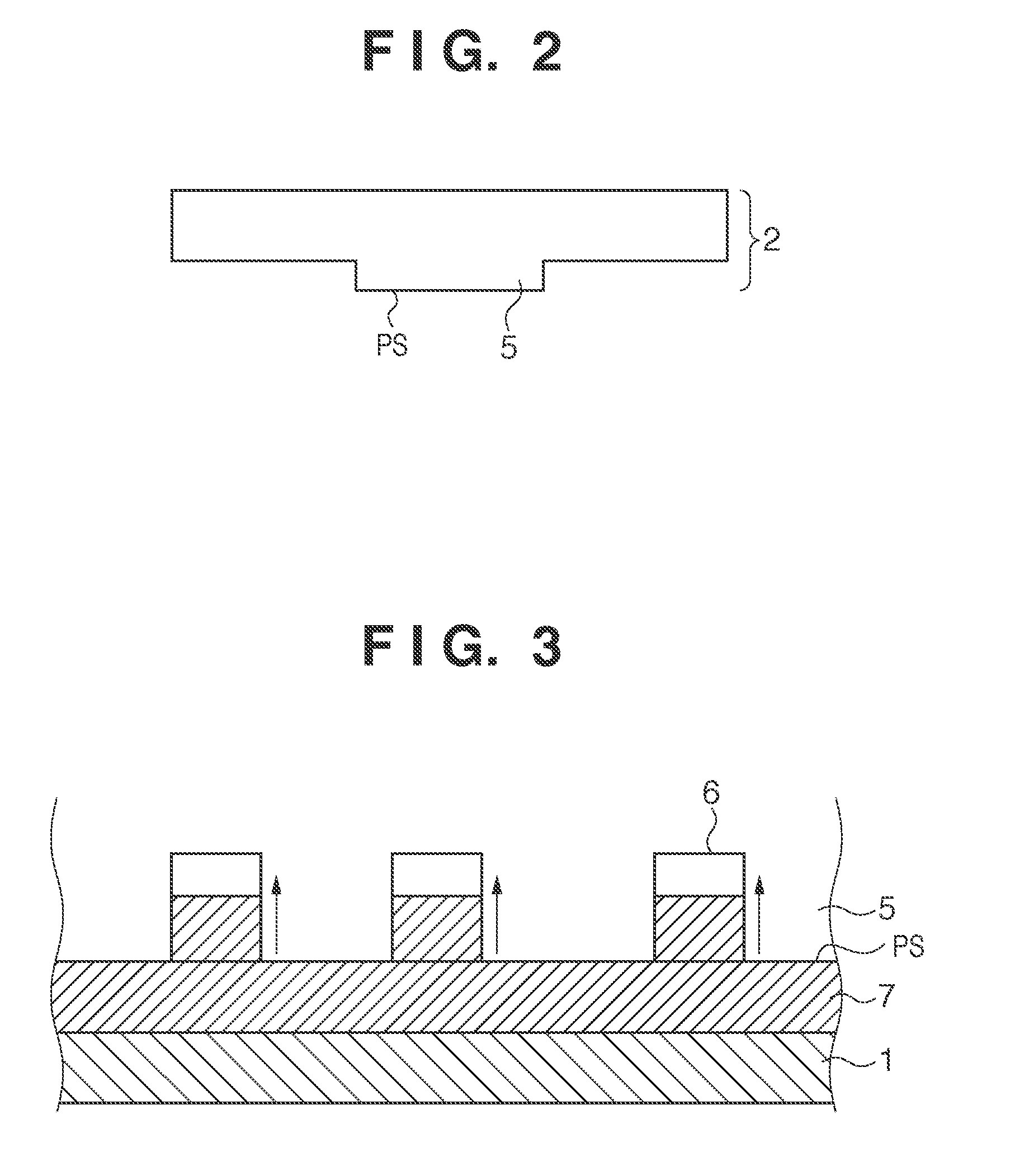
[0024]FIG. 1B shows the schematic arrangement of an imprint apparatus 100′ according to the second embodiment of the present invention. The same reference numerals as in the constituent elements of the imprint apparatus 100 according to the first embodiment denote the same constituent elements in FIG. 1B. The imprint apparatus 100′ according to the second embodiment has an arrangement in which the supply portion 16 in the imprint apparatus 100 according to the first embodiment is replaced with a gas controller 18. Although a mold 2 can have an arrangement similar to that in the first embodiment, it is preferably covered with a non-porous member 9 in a portion other than a pattern portion 5. FIG. 5A shows one example of the mold 2 which can be used in the second embodiment. The gas controller 18 includes a suction portion which draws the gas in concave portions 6 of the pattern by suction via a porous portion 8 that forms the pattern portion 5 of the mold 2, while the pattern portion...


PUM

PropertyMeasurementUnit
thicknessaaaaaaaaaa
timeaaaaaaaaaa
thicknessaaaaaaaaaa

Abstract

An imprint apparatus which cures a resin dispensed on a substrate while the resin and a pattern surface of a mold are in contact with each other, comprises a supply portion configured to supply a gas, used to accelerate filling of a concave portion of the pattern surface of the mold with the resin, to a space which the pattern surface of the mold faces, and a controller configured to control the supply portion to supply the gas to the space before the resin and the pattern surface of the mold are brought into contact with each other, wherein the supply portion is configured to supply the gas to the space via a porous portion formed in at least part of the mold.

Description

BACKGROUND OF THE INVENTION[0001]1. Field of the Invention[0002]The present invention relates to an imprint apparatus, and a method of manufacturing an article using the imprint apparatus.[0003]2. Description of the Related Art[0004]Imprint techniques are coming into practical use as one type of lithographic technique intended for mass production of magnetic storage media and semiconductor devices. An imprint technique of forming a pattern on the order of nanometers is known as a nanoimprint technique. Imprint techniques involve a mold (original) on which a pattern is formed that is pressed against a resin dispensed on a substrate such as a silicon wafer or a glass plate. The resin is cured in this state, thereby transferring the pattern onto the substrate.[0005]The conventional imprint methods pose problems in that it takes a long time to fill concave portions of the pattern formed on the mold with the resin, and that a defect occurs if a curing process is executed before the conca...

Claims


Application Information

Patent Timeline
Patent Type & Authority Applications(United States)
IPC IPC(8): B05D3/12B05D3/04B05C11/00
CPCB82Y10/00B29C59/02G03F7/0002B82Y40/00B29C33/3885B29C35/0233H01L21/0274
Inventor SATO, HIROSHIINA, HIDEKI
Owner CANON KK
Why Eureka
Try Eureka