Motor-driven centrifugal compressor

a centrifugal compressor and motor technology, applied in the direction of positive displacement liquid engines, piston pumps, bearing cooling, etc., can solve the problems of difficult operation of the supercharger at temperatures below the heat-resistant temperature of the magnets of the electric motor, iron loss of the rotor, etc., to achieve efficient removal of heat, simple and compact structure, and suitably high speed rotation

Inactive Publication Date: 2011-10-06
HONDA MOTOR CO LTD
View PDF3 Cites 66 Cited by
  • Summary
  • Abstract
  • Description
  • Claims
  • Application Information

AI Technical Summary

Benefits of technology

[0010]It is an object of the present invention to provide a motor-driven centrifugal compressor which is simple and compact in st

Problems solved by technology

However, when the rotational shaft 3 is rotated at a high speed, the iron loss of the rotor 5a increases, thus making it diff

Method used


Image

  • Motor-driven centrifugal compressor
  • Motor-driven centrifugal compressor
  • Motor-driven centrifugal compressor

Examples


Embodiment Construction

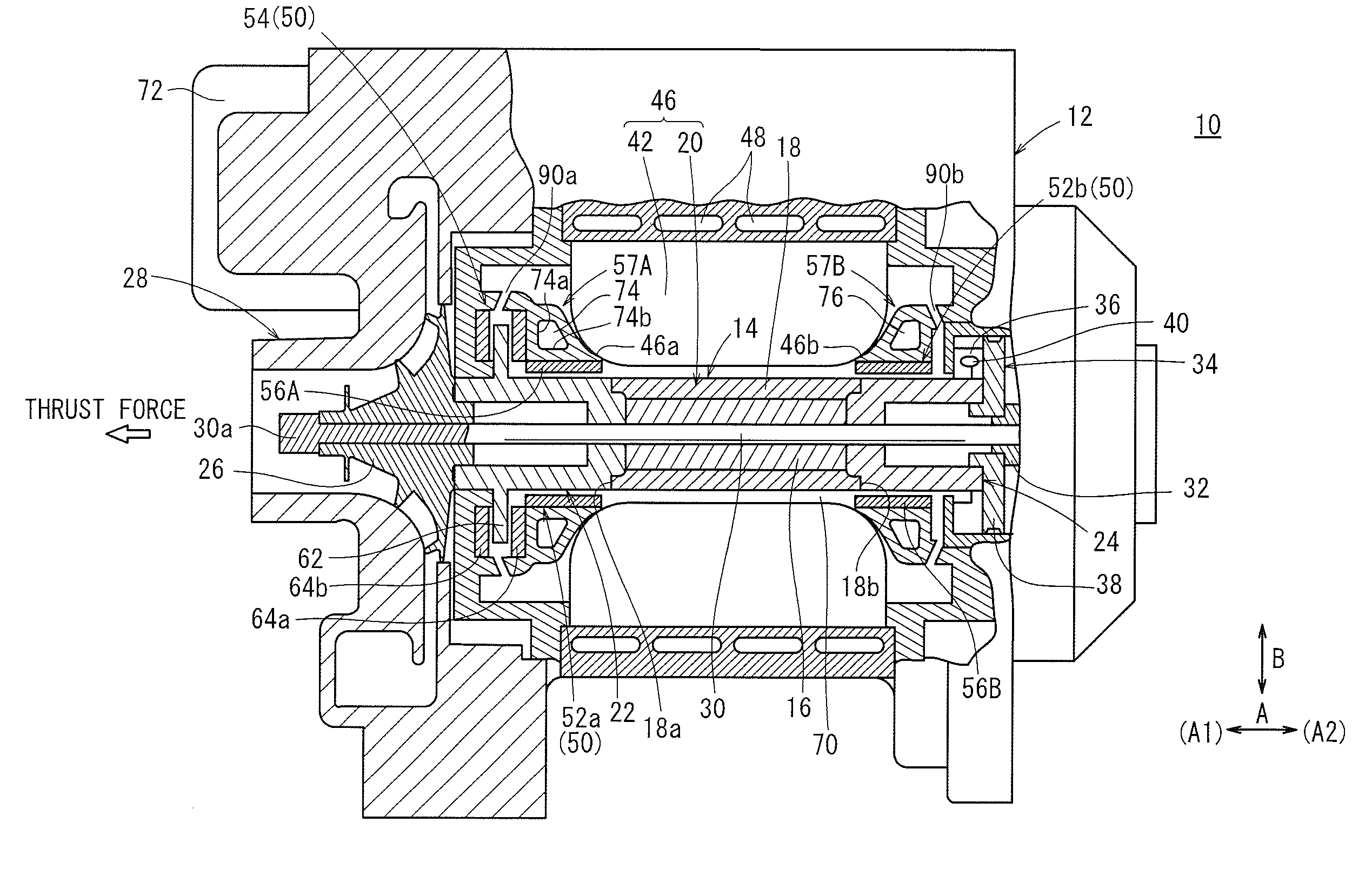
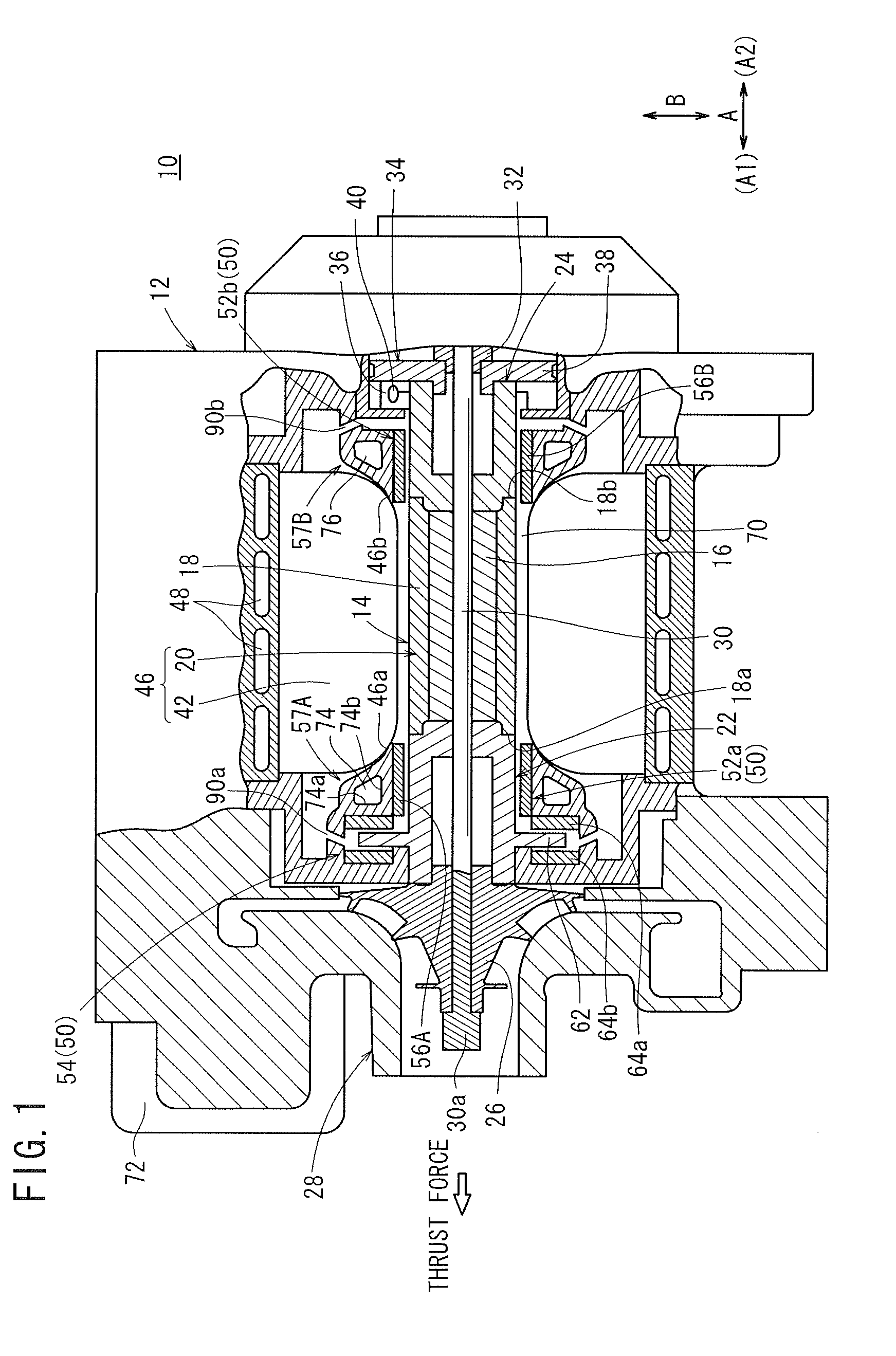
[0025]As shown in FIG. 1, a motor-driven centrifugal compressor 10 according to an embodiment of the present invention includes a casing 12 in which a rotatable shaft unit 14 is rotatably mounted.

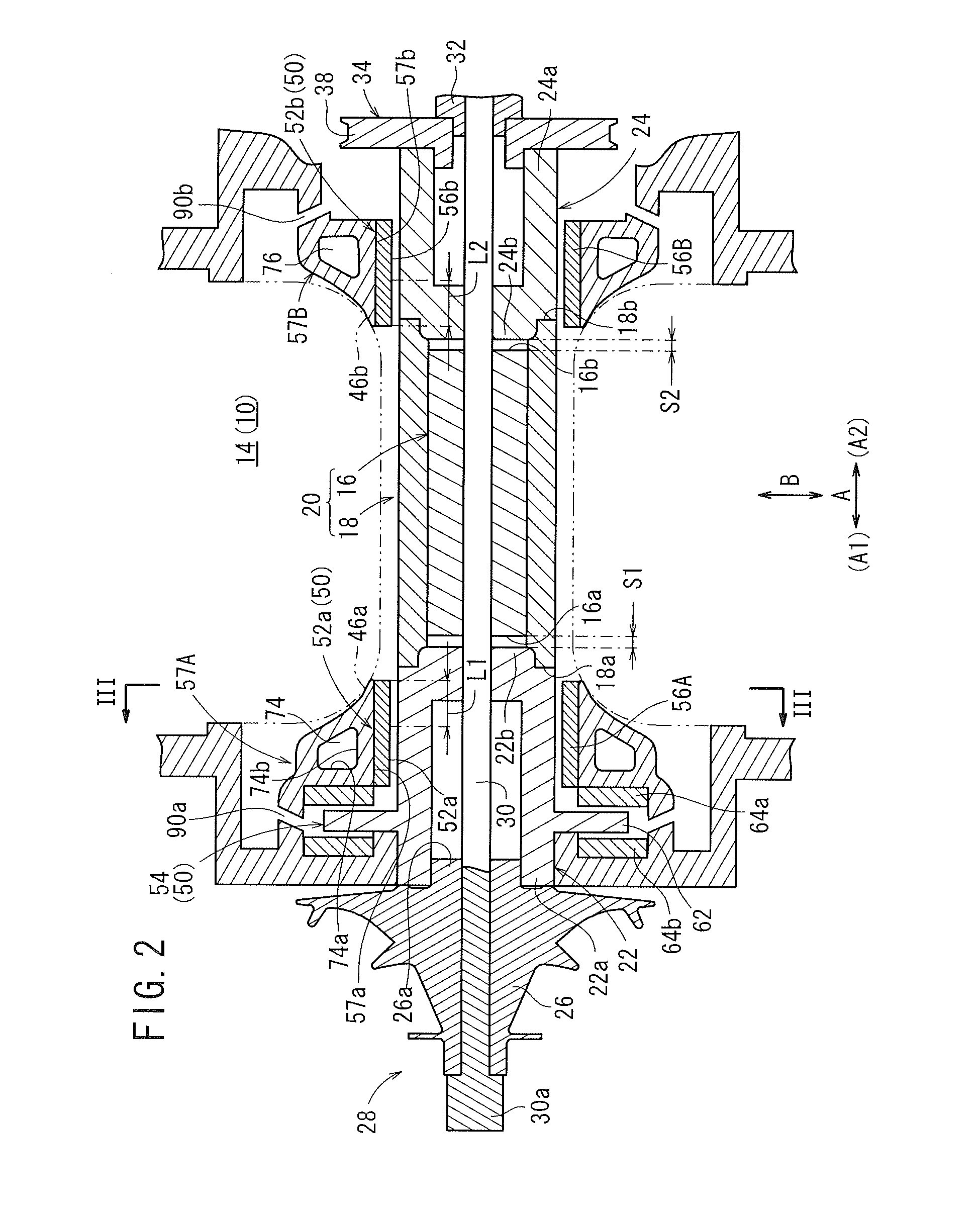
[0026]As shown in FIGS. 1 and 2, the rotatable shaft unit 14 comprises a rotor 20 having an annular permanent magnet 16 and a hollow cylindrical protective sleeve 18 disposed around the permanent magnet 16 and housing therein the permanent magnet 16, which may be shrink-fit in the protective sleeve 18, for example, a pair of bearing shafts 22, 24 mounted on respective axial opposite ends as rotatable members, in particular, rotatable shafts, and an impeller 26 mounted on the axial end of the bearing shaft 22 that is remote from the rotor 20.

[0027]The impeller 26 serves as part of a centrifugal compression unit 28 and has an end face held against a large-diameter end 30a of a tension shaft 30. The tension shaft 30 which extends axially through the impeller 26 supports thereon the bearing sha...


PUM


Abstract

A motor-driven centrifugal compressor includes a journal air bearing having a bump foil and a top foil for restraining a bearing shaft in a resting state and forming an air layer between the top foil and the bearing shaft in a rotating state. The top foil and the bump foil are fixed to an inner circumferential surface of a ring member, which is fixed to an inner circumferential surface of a first stationary holding member of the ring member. The first stationary holding member has a coolant water channel defined therein. The bearing shaft, the air layer, the top foil, the bump foil, and the coolant water channel are arranged in the order named along a normal direction.

Description

CROSS-REFERENCE TO RELATED APPLICATION[0001]This application is based upon and claims the benefit of priority from Japanese Patent Application No. 2010-083873 filed on Mar. 31, 2010, of which the contents are incorporated herein by reference.BACKGROUND OF THE INVENTION[0002]1. Field of the Invention[0003]The present invention relates to a motor-driven centrifugal compressor for compressing air and supplying the compressed air by driving of an electric motor.[0004]2. Description of the Related Art[0005]Generally, motor-driven centrifugal compressors are used as superchargers for efficiently supplying compressed air. For example, motor-driven centrifugal compressors are used as an auxiliary for supplying compressed air to an engine or as an auxiliary for supplying compressed air as an oxygen-containing gas to a fuel cell.[0006]A supercharger for use with a fuel cell which is disclosed in Japanese Laid-Open Patent Publication No. 2007-092646 is known as such a motor-driven centrifugal ...

Claims


Application Information

Patent Timeline
IPC IPC(8): F04B17/00F16C32/06
CPCF04D25/0606F04D29/057F04D29/584F16C17/024F16C17/10F16C37/002F02B33/40F16C17/042F02B39/10F04D29/0513
Inventor DAIKOKU, KENSUKESATO, TAKAHARU
Owner HONDA MOTOR CO LTD
Why Eureka
Try Eureka