
Ceramic beads with smooth surfaces and process for producing the same

a technology of ceramic beads and smooth surfaces, applied in the field of ceramic beads, can solve the problems of difficult to sufficiently round the particles, low wear resistance, etc., and achieve the effect of satisfactory shape, less apt to burst, and efficient production

Active Publication Date: 2011-10-06
TOSOH CORP
View PDF5 Cites 0 Cited by
  • Summary
  • Abstract
  • Description
  • Claims
  • Application Information

AI Technical Summary

Benefits of technology

[0014]According to the invention, spherical ceramic beads with smooth surfaces are easily obtained from a raw-material ceramic powder. Furthermore, even when the raw-material powder has pores therein, the powder particles are less apt to burst. Consequently, ceramic beads of a satisfactory shape can be efficiently obtained in high yield.

Problems solved by technology

However, this method has had a problem that particles distributed in the region which surrounds the thermal plasma and through which a sheath gas is flowing remain unmelted and come to coexist as particles having low wear resistance.
However, these methods not only involve a complicated process but also have had a drawback that when the raw-material powder has pores therein, the particles burst upon melting or voids are formed through melting, which constitutes an obstacle that makes it difficult to sufficiently round the particles.

Method used


Image

  • Ceramic beads with smooth surfaces and process for producing the same
  • Ceramic beads with smooth surfaces and process for producing the same
  • Ceramic beads with smooth surfaces and process for producing the same

Examples


example 1

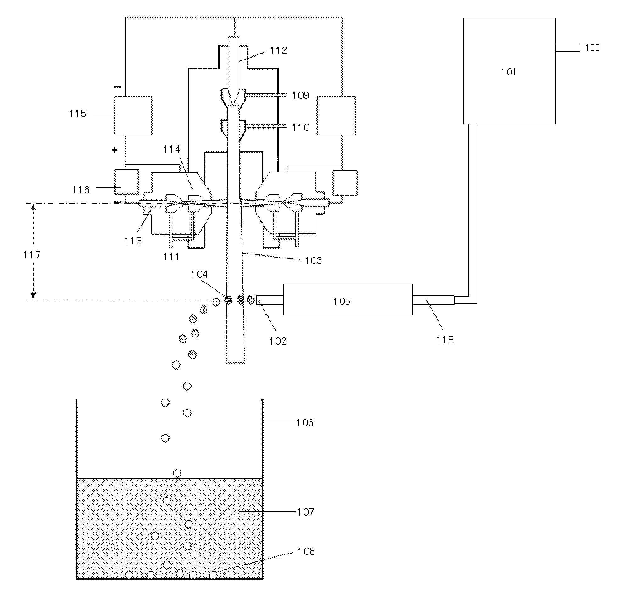
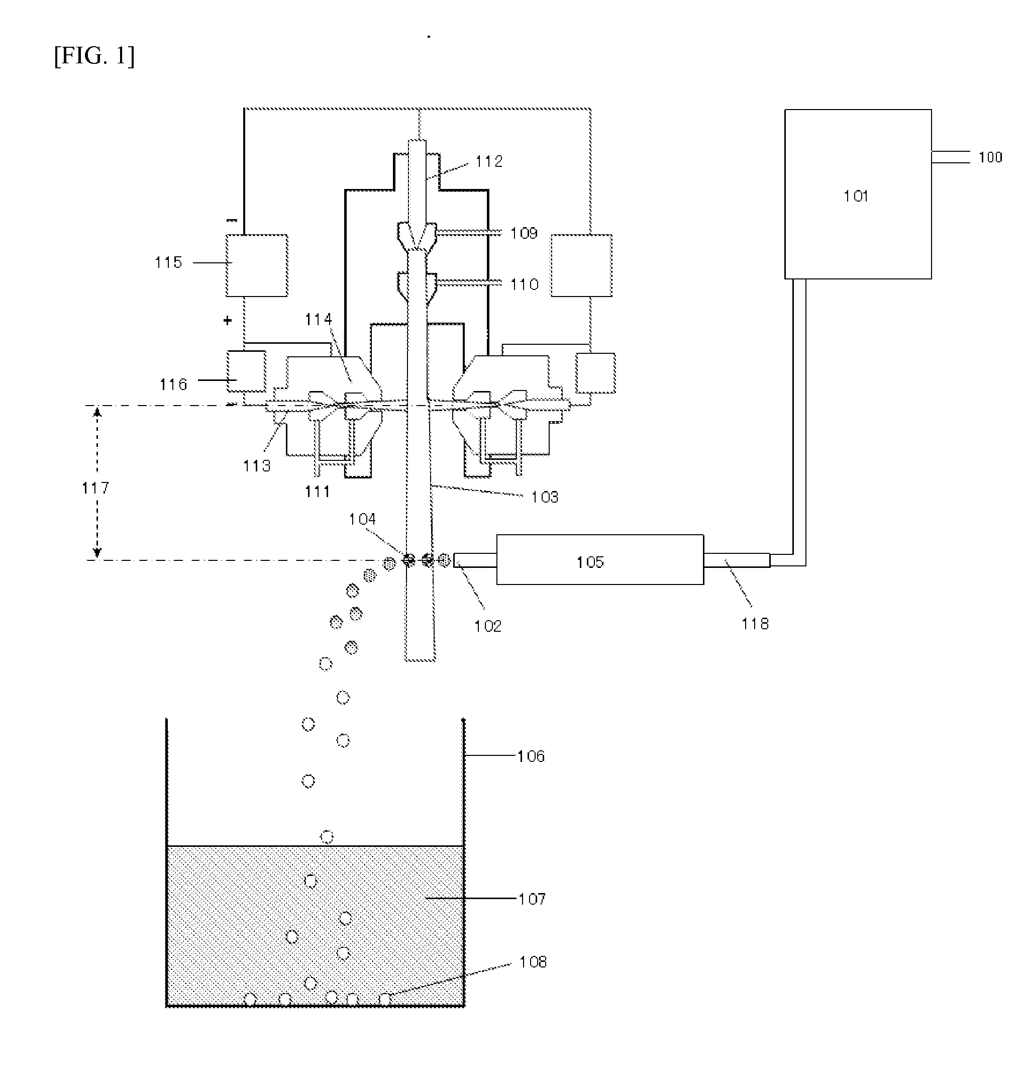
[0116]Ceramic beads were produced using the apparatus configuration shown in FIG. 1.

[0117]An yttria-containing (3% by mole) partially stabilized zirconia powder which had an average particle diameter of 50 μm and which had been obtained through granulation by an in-liquid granulation method and through sintering was introduced as a raw material into the powder feeder 101. A laminar-flow thermal plasma was generated while feeding argon gas 109, argon gas 111, and a plasma gas 110 composed of nitrogen and 20% hydrogen added thereto, at rates of 3.0 SLM, 2 SLM, and 6 SLM, respectively, and supplying an electric power at 24 kW (160 V×150 A).

[0118]Subsequently, the raw-material powder was supplied with a carrier gas 100, which was nitrogen introduced at 6 SLM, by means of the powder feed 101 at a rate of 20 g / min into a quartz pipe 118 having an inner diameter of 2 mm disposed in a tubular electric furnace 105 having a length of 1 m and having a temperature regulated to 1,000° C. The hea...

example 2

[0124]The powder was supplied for 10 minutes under the same conditions as in Example 1, except that the nitrogen carrier gas 100 was introduced at 4 SLM. The flow rate of the carrier gas being ejected in this operation was estimated at 90 m / sec using equation (1), and the discharge angle was 71°. The partially stabilized zirconia beads obtained were taken out by filtration and dried.

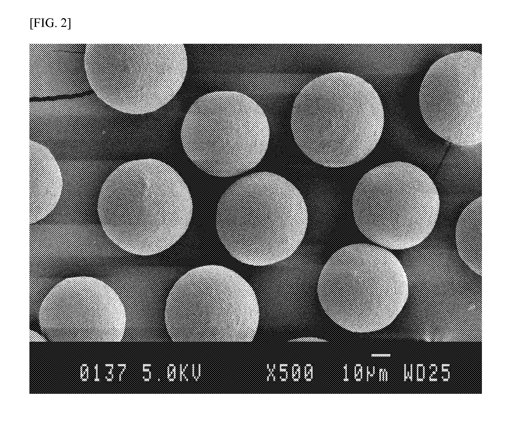
[0125]The surfaces and sections of the partially stabilized zirconia beads obtained were examined with an SEM. As a result, it was found that most of the fine grains on the bead surfaces had disappeared as a result of melting and the surfaces had been smoothed. A more even spherical shape was thus obtained, and the proportion of smooth beads was 95% or higher. Neither surface crack defects nor bead breakage both attributable to a thermal shock was observed. The internal void ratio was 5%. Furthermore, the beads were evaluated for wear characteristics and, as a result, the amount of zirconia was found to ...

example 3

[0127]The powder was supplied for 10 minutes under the same conditions as in Example 1, except that the nitrogen carrier gas 100 was introduced at 10 SLM. The flow rate of the carrier gas being ejected in this operation was estimated at 230 m / sec using equation (1). The partially stabilized zirconia beads obtained were taken out by filtration and dried.

[0128]The surfaces and sections of the partially stabilized zirconia beads obtained were examined with an SEM. As a result, it was found that most of the fine grains on the bead surfaces had disappeared as a result of melting and the surfaces had been smoothed. A more even spherical shape was thus obtained, and the proportion of smooth beads was 95% or higher. Neither surface crack defects nor bead breakage both attributable to a thermal shock was observed. The internal void ratio was 3%. Furthermore, the beads were evaluated for wear characteristics and, as a result, the amount of zirconia was found to be 0.1 ppm, which was a detecti...


PUM

PropertyMeasurementUnit
Raaaaaaaaaaa
surface roughnessaaaaaaaaaa
particle diameteraaaaaaaaaa

Abstract

A subject for the invention is to provide a process for ceramic bead production in which ceramic beads with smooth surfaces are obtained by a simpler method without using a complicated process involving, for example, a DC plasma / radio-frequency plasma combination or a two-stage radio-frequency plasma. Another subject is to provide such ceramic beads. The invention relates to a technique in which a preheated raw ceramic material is introduced into a laminar-flow thermal plasma obtained using a high-voltage type direct-current (DC) plasma gun and is cooled and solidified and the resultant ceramic beads are collected. It is preferred that the raw ceramic material should be preheated by passing the raw material through a refractory tube which runs through a furnace, while sending the raw ceramic material with a carrier gas, and that the preheated raw-material powder should be introduced into and treated with the thermal plasma under such conditions that the resultant ceramic beads are discharged from the thermal plasma at a discharge angle of 60° or larger with the thermal plasma. Thus, satisfactory ceramic beads which have smooth surfaces and have few crack defects and few internal void defects are obtained.

Description

TECHNICAL FIELD[0001]The present invention relates to ceramic beads suitable for use in, for example, bead mills, and to a process for producing the ceramic beads.BACKGROUND ART[0002]A bead mill method is known as a technique for mixing and / or disaggregating a fine ceramic powder (see, for example, patent document 1). Beads for use in bead mills are required to have high wear resistance in order to minimize contamination caused by the bead material as a result of bead wear (see, for example, patent documents 2 and 3).[0003]A technique for producing a spherical powder using a thermal plasma has been disclosed as one method for enhancing the wear resistance of beads (see, for example, patent documents 4 and 5). In such techniques for producing a spherical powder using a thermal plasma, a radio-frequency plasma is in main use because the plasma is generated in a wide region (see, for example, patent documents 5, 6, and 7). In the radio-frequency plasma method, particles which have pass...

Claims


Application Information

Patent Timeline
Patent Type & Authority Applications(United States)
IPC IPC(8): B32B3/00H05B6/00
CPCB01J19/088B01J2219/0879B01J2219/0894C01G25/02C04B35/486C04B35/62665Y10T428/2982C04B2235/3246C04B2235/528C04B2235/5436C04B2235/5481C04B2235/77C04B2235/963C04B2235/3225B01J19/08C04B35/48
Inventor KOHGO, MASANORITAKAHASHI, KOYATA
Owner TOSOH CORP
Learn More