Membrane electrode assembly for fuel cell and fuel cell using the same

a fuel cell and membrane electrode technology, applied in the direction of solid electrolyte fuel cells, fuel cells, cell components, etc., can solve the problems of initial deterioration of power generation performance, overvoltage of cathodes, and problems such as the inability to use direct oxidation fuel cells such as dmfcs, and achieve good durability and sufficient oxidant gas diffusion

Inactive Publication Date: 2011-10-06
PANASONIC INTELLECTUAL PROPERTY MANAGEMENT CO LTD
View PDF2 Cites 5 Cited by
  • Summary
  • Abstract
  • Description
  • Claims
  • Application Information

AI Technical Summary

Benefits of technology

[0030]The invention allows the cathode diffusion layer to have an optimum pore structure having both the function of removing liquid water as viscous flow and the function of allowing an oxidant gas as diffusion flow to pass through. Hence, condensed water accumulated inside the pores of the cathode catalyst layer,

Problems solved by technology

Practical utilization of direct oxidation fuel cells such as DMFCs has some problems.
The water impairs the diffusion of the oxidant in the cathode, thereby causing the cathode concentration overvoltage to increase.
This is the main reason of initial deterioration of power generation performance of direct oxidation fuel cells.
In particular, when the water continues to accumulate inside the pores of the cathode diffusion layer and at the interface between the cathode catalyst layer and the cathode diffusion layer, the water inside the pores cannot be removed therefrom, and the supply of the oxidant through the pores to the three-phase interface, which is the electrode reaction site, is impeded.
As a result, it is difficult to maintain power generation.
Further, the initial deterioration is strongly affected by fuel crossover, which is a phenomenon of unreacted organic fuel passing through the electrolyte membrane and reaching the cathode.
Thus,

Method used


Image

  • Membrane electrode assembly for fuel cell and fuel cell using the same
  • Membrane electrode assembly for fuel cell and fuel cell using the same
  • Membrane electrode assembly for fuel cell and fuel cell using the same

Examples


example 1

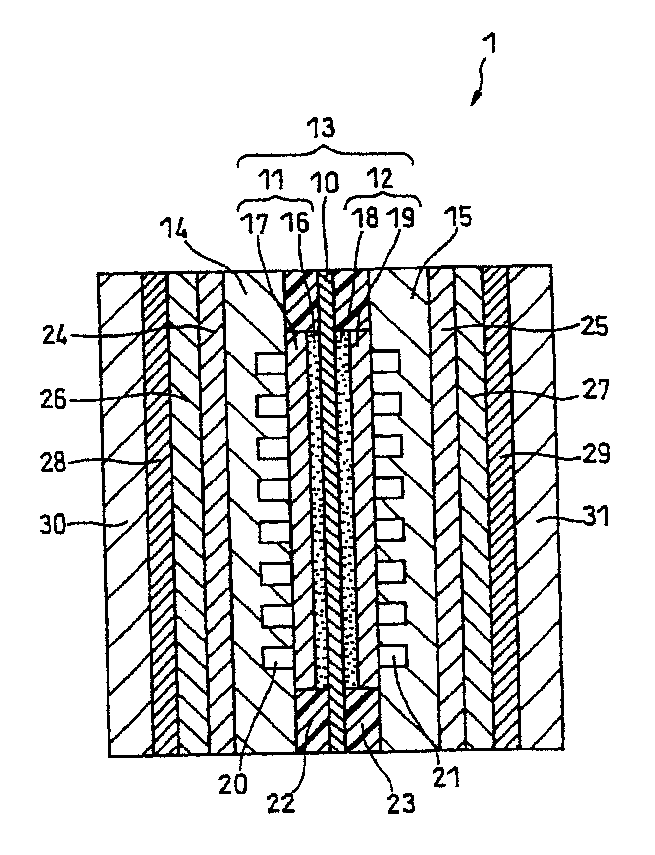
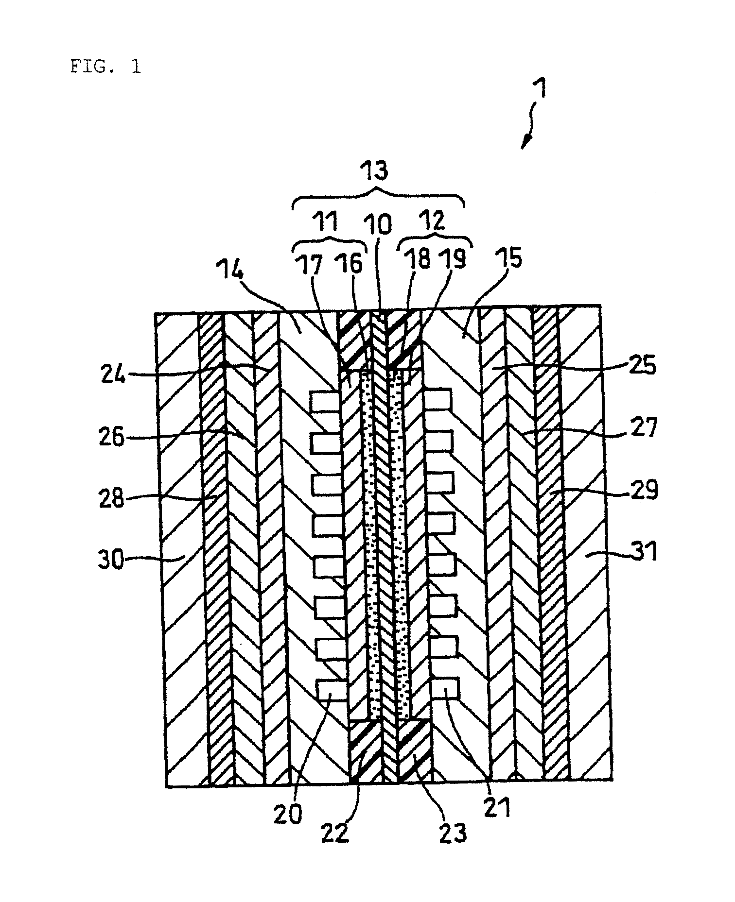
[0109]A fuel cell as illustrated in FIGS. 1 and 2 was produced.

(Preparation of Anode Catalyst Layer)

[0110]Pt—Ru alloy fine particles with a mean particle size of 3 nm (Pt:Ru weight ratio=2:1) were used as the anode catalyst.

[0111]The anode catalyst was ultrasonically dispersed in an aqueous solution of isopropanol. To the resulting dispersion was added an aqueous solution containing 5% by weight of a polymer electrolyte. The resulting mixture was stirred with a disperser to prepare an anode catalyst ink. The weight ratio of the Pt—Ru alloy fine particles to the polymer electrolyte in the anode catalyst ink was set to 3:1. The polymer electrolyte used was a perfluorocarbon sulfonic acid ionomer (Flemion available from Asahi Glass Co., Ltd.).

[0112]Subsequently, the anode catalyst ink was applied onto a predetermined region of a surface of an electrolyte membrane 10 by using a spray coater and then dried to form an anode catalyst layer 16 with a size of 6 cm×6 cm. The amount of the Pt—...

example 2

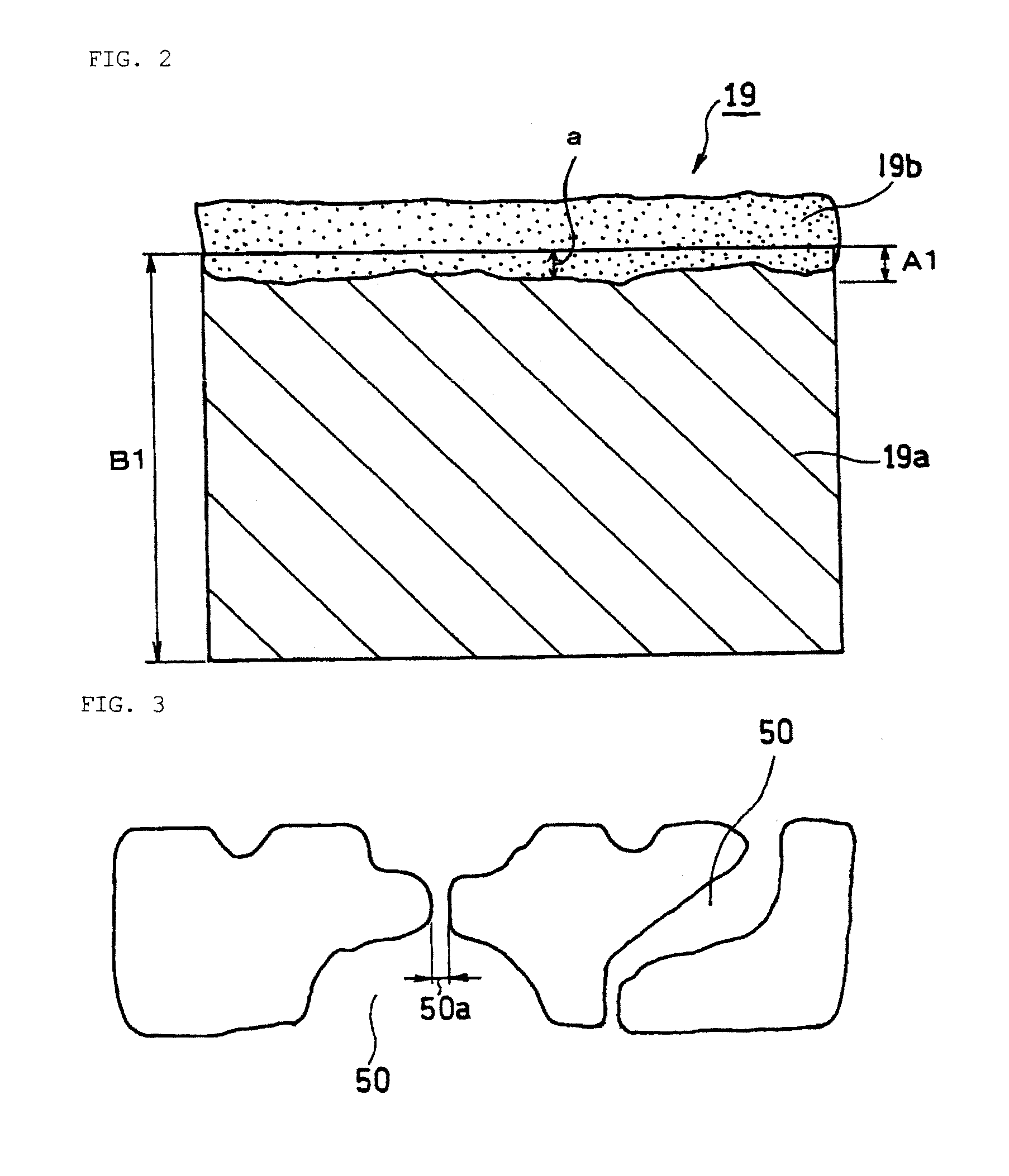
[0131]A fuel cell B was produced in the same manner as in Example 1, except that in the preparation of a cathode diffusion layer, the amount of the porous composite layer per projected unit area was set to 0.9 mg / cm2. The amount of the porous composite layer was adjusted by decreasing the set gap of the doctor blade for applying the paste for forming the cathode porous composite layer onto a conductive porous substrate surface.

example 3

[0132]A fuel cell C was produced in the same manner as in Example 1, except that in the preparation of a cathode diffusion layer, the amount of the porous composite layer per projected unit area was set to 2.6 mg / cm2. The amount of the porous composite layer was adjusted by increasing the set gap of the doctor blade for applying the paste for forming the cathode porous composite layer onto a conductive porous substrate surface.


PUM


Abstract

A membrane electrode assembly for a fuel cell includes an anode, a cathode, and an electrolyte membrane disposed between the anode and the cathode. The cathode includes a cathode catalyst layer and a cathode diffusion layer disposed on the cathode catalyst layer. The cathode diffusion layer includes a conductive porous substrate and a porous composite layer disposed on a surface of the conductive porous substrate. The porous composite layer includes conductive carbon particles and a water-repellent binding material. The cathode diffusion layer has a plurality of through pores having a largest pore diameter of 15 to 20.5 μm and a mean flow pore diameter of 3 to 10.5 μm in pore throat size distribution determined by a half dry/bubble point method.

Description

RELATED APPLICATIONS[0001]This application is the U.S. National Phase under 35 U.S.C. §371 of International Application No. PCT / JP2010 / 006100, filed on Oct. 14, 2010, which in turn claims the benefit of Japanese Application No. 2009-239417, filed on Oct. 16, 2009, the disclosures of which Applications are incorporated by reference herein.TECHNICAL FIELD[0002]This invention relates to membrane electrode assemblies for fuel cells, and specifically to an improvement in the cathode diffusion layer of a membrane electrode assembly for a fuel cell.BACKGROUND ART[0003]An energy system using a fuel cell has been proposed as a means for solving the environmental problems such as global warming and air pollution and the problem of depletion of resources and realizing a sustainable recycling society.[0004]Examples of fuel cells include stationary fuel cells installed in factories and houses and non-stationary fuel cells used as the power source for automobiles, portable electronic appliances, ...

Claims


Application Information

Patent Timeline
IPC IPC(8): H01M8/10H01M8/04
CPCH01M8/1002H01M8/1011Y02E60/523H01M4/8663H01M4/8605H01M8/1007Y02E60/50
Inventor UEDA, HIDEYUKI
Owner PANASONIC INTELLECTUAL PROPERTY MANAGEMENT CO LTD
Why Eureka
Try Eureka