Organic el display unit, method of manufacturing the same, and solution used in method

a technology of organic el and display unit, which is applied in the direction of electroluminescent light sources, chemistry apparatuses and processes, and compositions. it can solve the problems of reducing the emission efficiency of the red organic el device and the green organic el device, the light emitting characteristics the emission efficiency of the blue organic el device, so as to improve the efficiency of hole injection into the first organic light emitting layer, improve the emission efficiency and life characteristics

Active Publication Date: 2011-10-13
JOLED INC
View PDF1 Cites 139 Cited by
  • Summary
  • Abstract
  • Description
  • Claims
  • Application Information

AI Technical Summary

Benefits of technology

[0018]According to the organic EL display device and the method of manufacturing the organic EL display device, the second hole injection/transport layer made of a low molecular material is formed by evaporation method on the entire surface of the first hole injection/transport layer for the blue first organic EL device and the second organic light emitting layer of the first color. Thereby, the interface with the blue organic light emitting layer is improved, and efficiency of hole injection into the first organic light emitting layer is improved. In the result, emission efficiency and life characteristics of the first organic EL device are able to be improved. Thus, further increased emission efficien

Problems solved by technology

However, the organic EL display unit formed by the method disclosed in Japanese Unexamined Patent Application Publication No. 2006-140434 has two significant issues in terms of practical use.
One issue is the light emitting characteristics of the blue organic EL device.
A s

Method used


Image

  • Organic el display unit, method of manufacturing the same, and solution used in method
  • Organic el display unit, method of manufacturing the same, and solution used in method
  • Organic el display unit, method of manufacturing the same, and solution used in method

Examples


first embodiment (

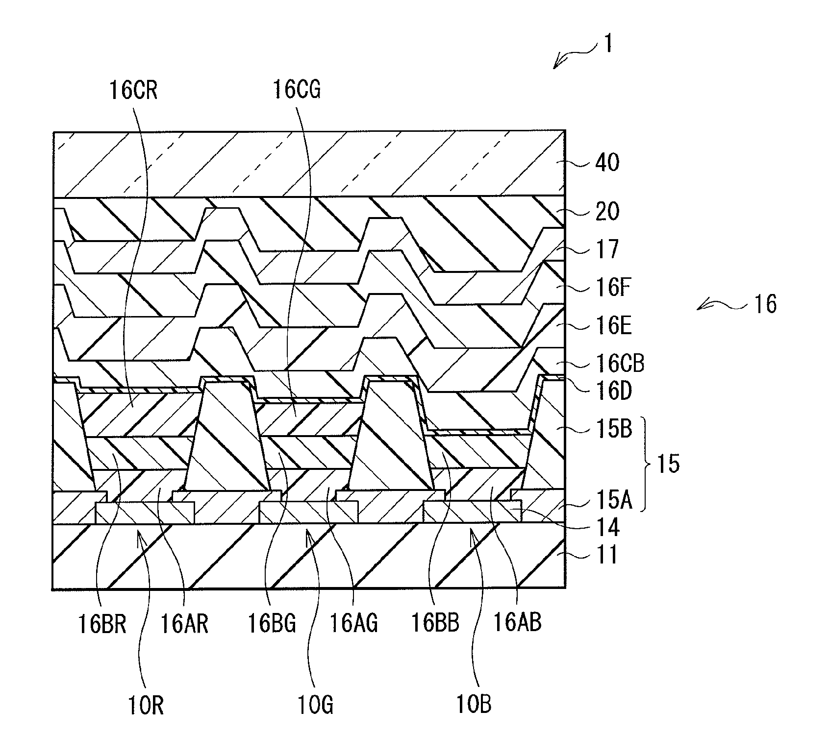
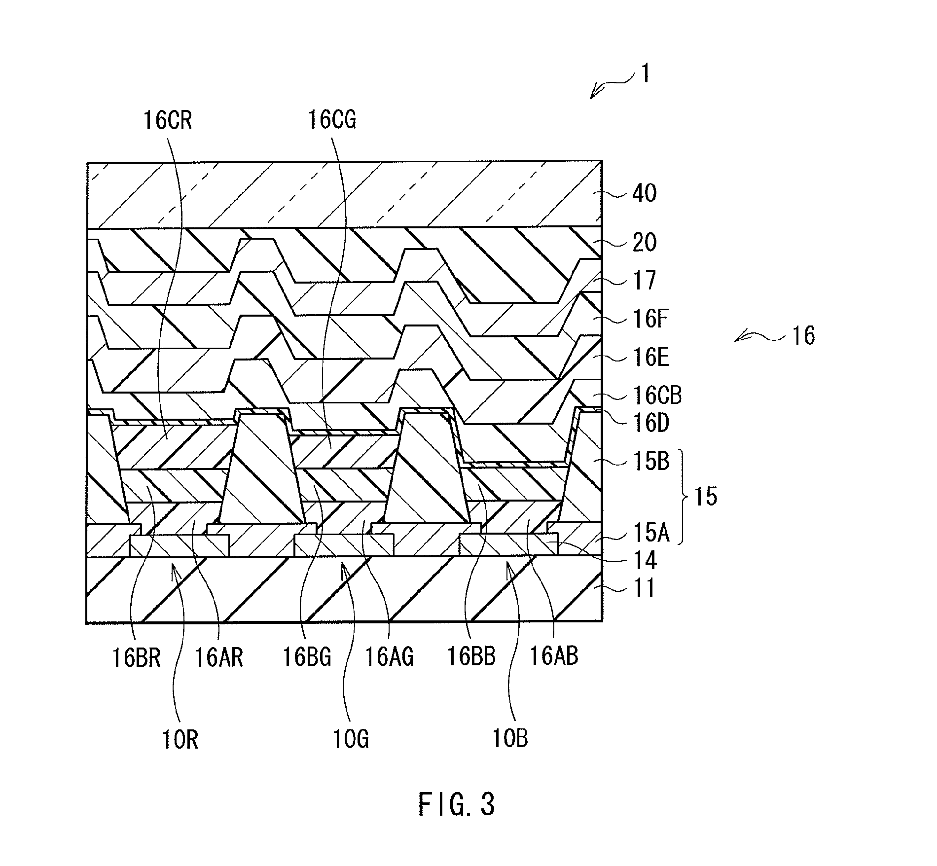
1. First embodiment (an organic EL display unit in which a second hole injection / transport layer is formed on a red / green light emitting layer and a blue hole transport layer)

second embodiment (

2. Second embodiment (an organic EL display unit in which a blue hole transport layer is not provided, and a second hole injection / transport layer is formed on a blue hole injection layer)

first embodiment

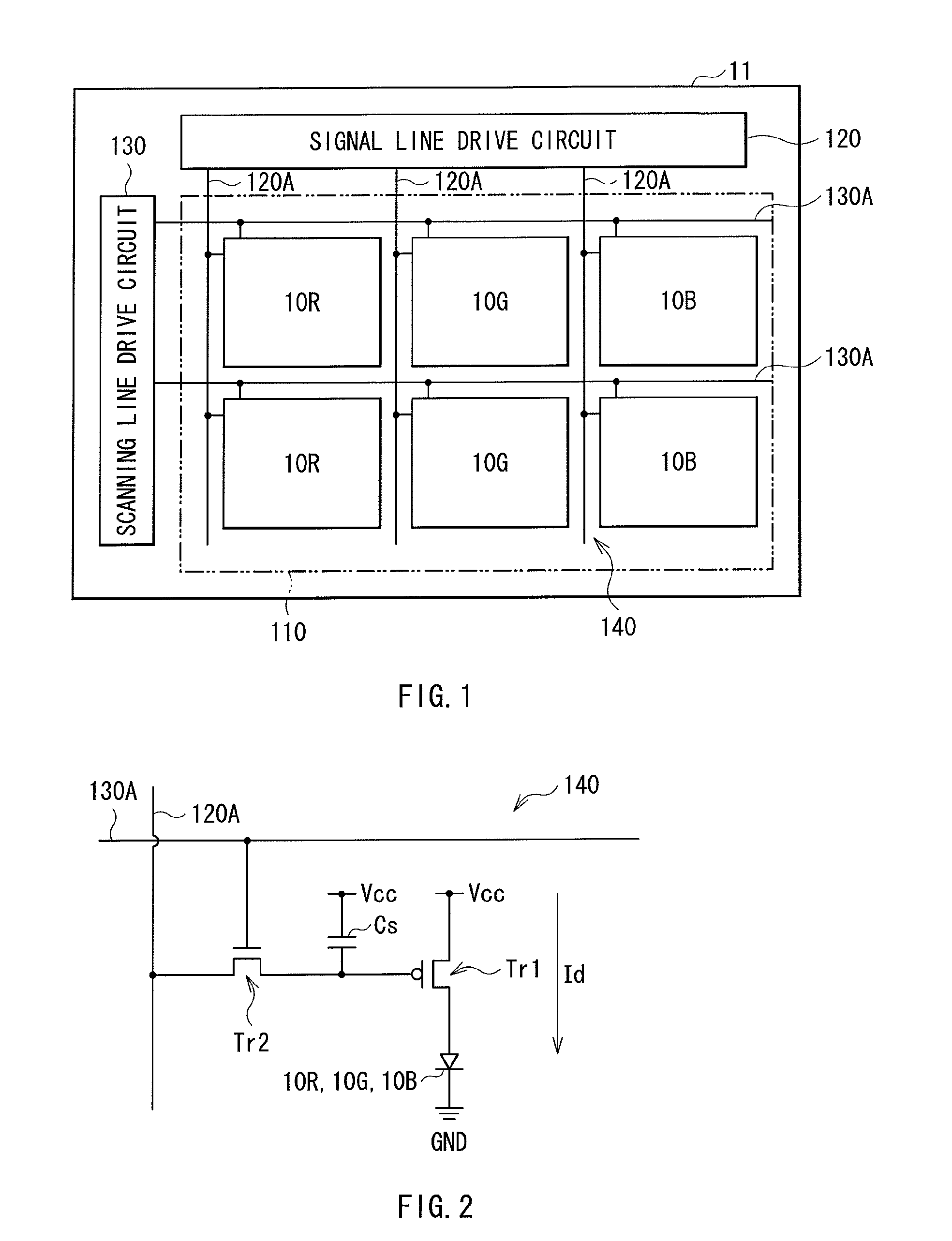
[0036]FIG. 1 illustrates a configuration of an organic EL display unit according to a first embodiment of the present invention. The organic EL display unit is used as an organic EL television device and the like. In the organic EL display unit, for example, as a display region 110, a plurality of red organic EL devices 10R, green organic EL devices 10G, and blue organic EL devices 10B, described hereinafter, are arranged in matrix form on a substrate 11. A signal line drive circuit 120 and a scanning line drive circuit 130 that are drivers for picture display are provided in the periphery of the display region 110.

[0037]A pixel drive circuit 140 is provided within the display region 110. FIG. 2 illustrates an example of the pixel drive circuit 140. The pixel drive circuit 140 is an active drive circuit formed in a layer located below a lower electrode 14, described hereinafter. That is, the pixel drive circuit 140 has a drive transistor Tr1 and a writing transistor Tr2, a capacitor...


PUM


Abstract

An organic electroluminescence display unit includes: a lower electrode for each device; a first hole injection/transport layer provided on the lower electrode for each device; a second organic light emitting layer of the first color provided on the first hole injection/transport layer for the second organic electroluminescence device; a second hole injection/transport layer provided on the entire surfaces of the second organic light emitting layer and the first hole injection/transport layer for the first organic electroluminescence device, and being made of a low molecular material; a blue first organic light emitting layer provided on the entire surface of the second hole injection/transport layer; and an electron injection/transport layer having at least one of electron injection characteristics and electron transport characteristics, and an upper electrode that are provided in sequence on the entire surface of first organic light emitting layer.

Description

BACKGROUND OF THE INVENTION[0001]1. Field of the Invention[0002]The present invention relates to an organic electroluminescence (EL) display unit that emits light using organic EL phenomenon, and a method of manufacturing the organic EL display unit.[0003]2. Description of the Related Art[0004]As development of the information communication industry accelerates, there is a demand for display devices having advanced performance. Organic EL devices that are receiving attention as next-generation display devices have the advantage of not only having a wide viewing angle and superior contrast as a spontaneous-emission display device, but also having a fast response time.[0005]A light emitting layer and the like composing the organic EL device are largely classified into low molecular materials and polymer materials. The low molecular materials are generally known to indicate higher emission efficiency and longer life, and are also considered to have, in particular, high blue-color capab...

Claims


Application Information

Patent Timeline
IPC IPC(8): H01L27/32H01L51/56
CPCC09K11/06C09K2211/1014C09K2211/1029C09K2211/1033C09K2211/1037C09K2211/1044C09K2211/1088C09K2211/1092H05B33/14H10K59/35H10K50/13H01L33/08H10K50/125H10K2102/00H10K71/00
Inventor MATSUMOTO, TOSHIKIHIGO, TOMOYUKIYOSHINAGA, TADAHIKOIMAI, TOSHIAKI
Owner JOLED INC
Why Eureka
Try Eureka