
Inspection Method and Apparatus, Lithographic Apparatus, Lithographic Processing Cell and Device Manufacturing Method

a technology of lithographic apparatus and manufacturing method, applied in the direction of photomechanical apparatus, instruments, printers, etc., can solve the problems of reducing the resistance thickness, affecting the accuracy of inspection, and using one-dimensional structures, etc., to achieve accurate focus values, improve the effect of inspection accuracy and reduced resistance thickness

Active Publication Date: 2011-10-13
ASML NETHERLANDS BV
View PDF11 Cites 52 Cited by
  • Summary
  • Abstract
  • Description
  • Claims
  • Application Information

AI Technical Summary

Benefits of technology

The present invention provides a method for measuring focus-related properties of an exposure apparatus by printing a pattern on a substrate surface using a patterning device designed to create a pattern that varies with variations in focus-related properties of the exposure apparatus. The pattern is then detected and measured for asymmetry, which is determined to be the focus-related property of the exposure apparatus. The invention also includes a mask for use in the exposure apparatus, a substrate with a printed pattern, and a projection apparatus for printing a pattern on a substrate. The invention also includes an inspection system for measuring focus-related properties of an exposure apparatus. The technical effects of the invention include improved focus metrology and accurate focus values even when resist thickness is reduced.

Problems solved by technology

However, there is a problem with this use of one-dimensional structures.
This means that focus and dose cannot be determined uniquely by measuring a single one-dimensional structure.
However, having a plurality of markers incorporating different structures has disadvantages, including occupying potentially valuable space on the substrate surface.
A decreased sensitivity may lead to the following unwanted effects: although the sensitivity level may decrease, the noise level does not decrease and as a result, the signal-to-noise ratio decreases and the side wall angle reproducibility may deteriorate accordingly; as modeling errors remain the same, this may lead to increased systematic accuracy errors in the side wall angle measurements; and, resist heights variations, or other variations in a stack that is part of the modeled pattern, may give rise to an undesired impact on the side wall angle measurements (also known as cross-talk).

Method used


Image

  • Inspection Method and Apparatus, Lithographic Apparatus, Lithographic Processing Cell and Device Manufacturing Method
  • Inspection Method and Apparatus, Lithographic Apparatus, Lithographic Processing Cell and Device Manufacturing Method
  • Inspection Method and Apparatus, Lithographic Apparatus, Lithographic Processing Cell and Device Manufacturing Method

Examples


Embodiment Construction

This specification discloses one or more embodiments that incorporate the features of this invention. The disclosed embodiment(s) merely exemplify the invention. The scope of the invention is not limited to the disclosed embodiment(s). The invention is defined by the claims appended hereto.

The embodiment(s) described, and references in the specification to “one embodiment”, “an embodiment”, “an example embodiment”, etc., indicate that the embodiment(s) described may include a particular feature, structure, or characteristic, but every embodiment may not necessarily include the particular feature, structure, or characteristic. Moreover, such phrases are not necessarily referring to the same embodiment. Further, when a particular feature, structure, or characteristic is described in connection with an embodiment, it is understood that it is within the knowledge of one skilled in the art to effect such feature, structure, or characteristic in connection with other embodiments whether o...


PUM

PropertyMeasurementUnit
wavelengthaaaaaaaaaa

Abstract

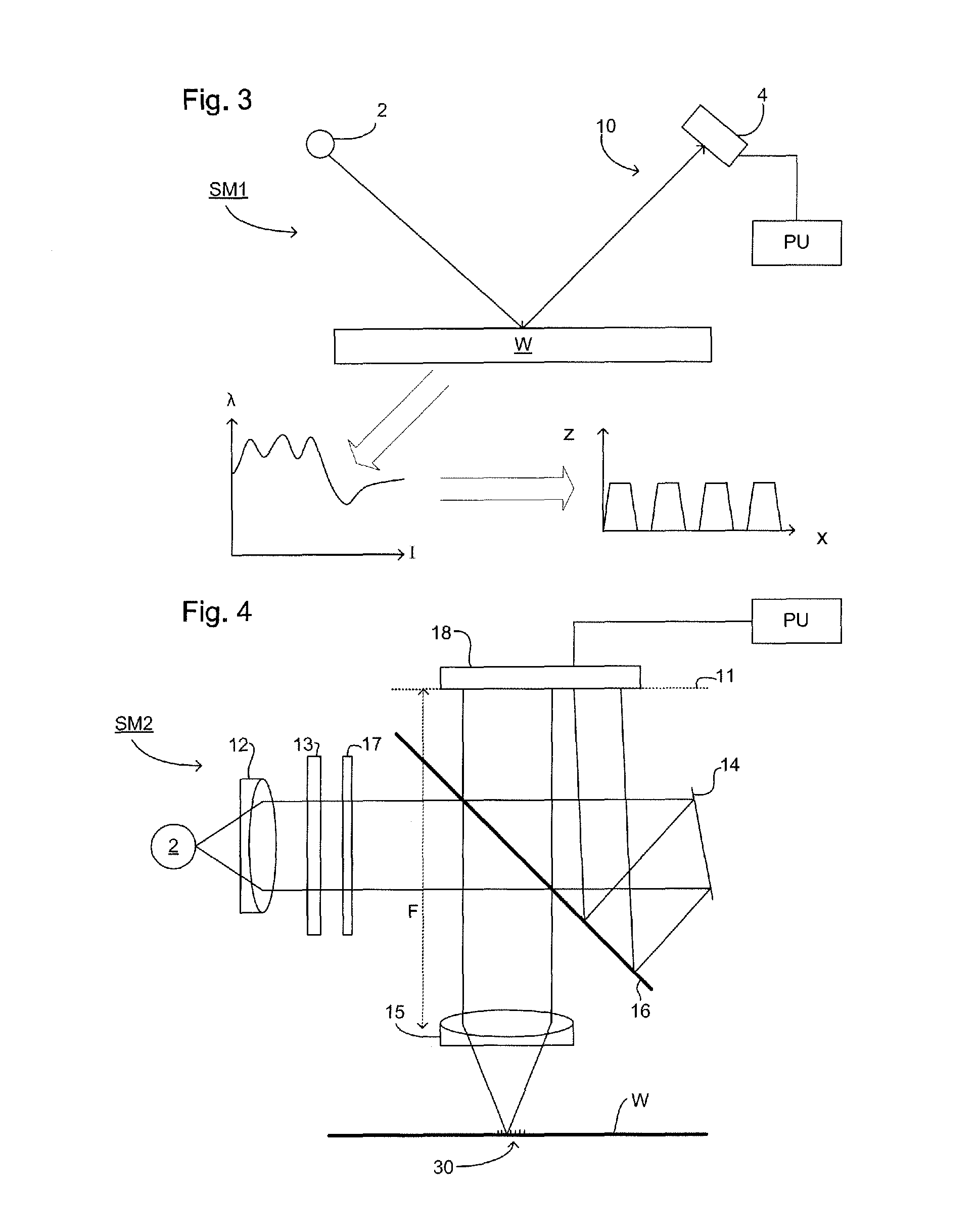
In order to determine whether an exposure apparatus is outputting the correct dose of radiation and a projection system of the exposure apparatus is focusing the radiation correctly, a test pattern is used on a mask for printing a specific marker onto a substrate. This marker may be measured by an inspection apparatus, such as, for example, a scatterometer to determine whether errors in focus, dose, and other related properties are present. The test pattern is arranged such that changes in focus and dose may be easily determined by measuring properties of a pattern that is exposed using the mask. The test pattern of the mask is arranged so that it gives rise to a marker pattern on the substrate surface. The marker pattern contains structures that have at least two measurable side wall angles. Asymmetry between side wall angles of a structure is related to focus (or defocus) of the exposure radiation from the exposure apparatus. The extent of defocus may thereby be determined by measuring an asymmetry in side wall angle of the printed marker pattern structures.

Description

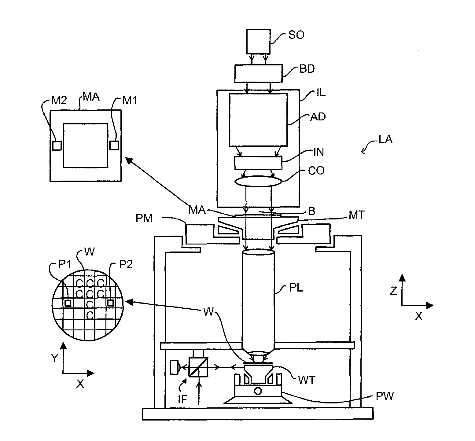
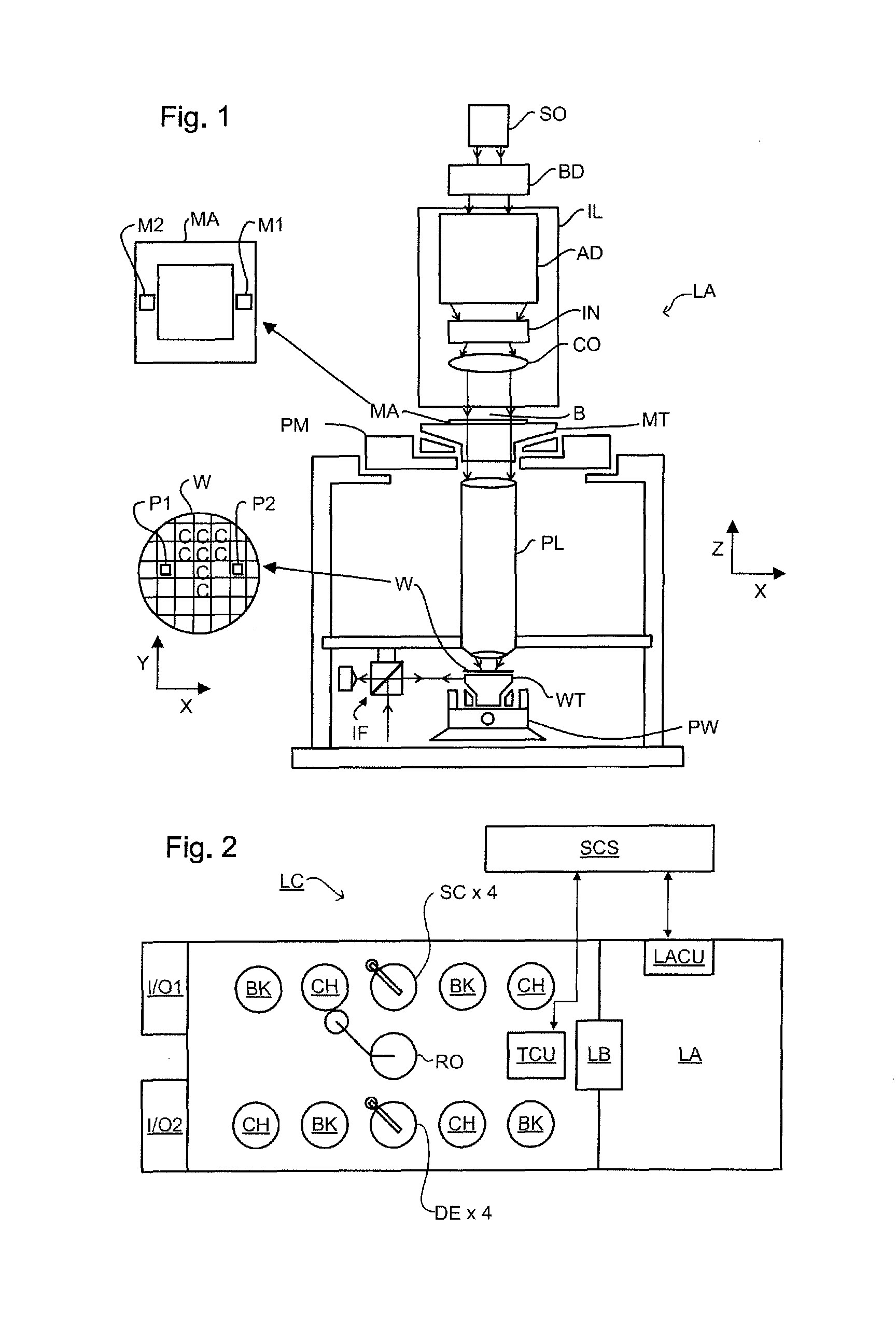
FIELDEmbodiments of the present invention relate to methods of inspection that may be used, for example, in the manufacture of devices by lithographic techniques and to methods of manufacturing devices using lithographic techniques, as well as to apparatus used to carry out the methods.BACKGROUNDA lithographic apparatus is a machine that applies a desired pattern onto a substrate, usually onto a target portion of the substrate. A lithographic apparatus can be used, for example, in the manufacture of integrated circuits (ICs). In that instance, a patterning device, which is alternatively referred to as a “mask” or a “reticle,” may be used to generate a circuit pattern to be formed on an individual layer of the IC. This pattern can be transferred onto a target portion (e.g., comprising part of, one, or several dies) on a substrate (e.g., a silicon wafer). Transfer of the pattern is typically via imaging onto a layer of radiation-sensitive material (i.e., resist) provided on the substr...

Claims


Application Information

Patent Timeline
Patent Type & Authority Applications(United States)
IPC IPC(8): G03B27/52B32B3/00G03F1/00
CPCG03F1/14G03F1/44Y10T428/24802G03F7/70641G03F7/70683G03F7/70625G03F7/2039H01L21/0273G03F1/62
Inventor CRAMER, HUGO AUGUSTINUS JOSEPHHINNEN, PAUL CHRISTIAAN
Owner ASML NETHERLANDS BV
Learn More