
Wireless conformal antenna system and method of operation

Active Publication Date: 2011-10-20
RF VENUE
View PDF17 Cites 5 Cited by
  • Summary
  • Abstract
  • Description
  • Claims
  • Application Information

AI Technical Summary

Benefits of technology

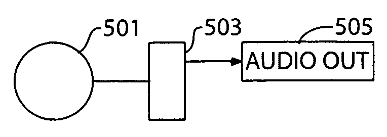
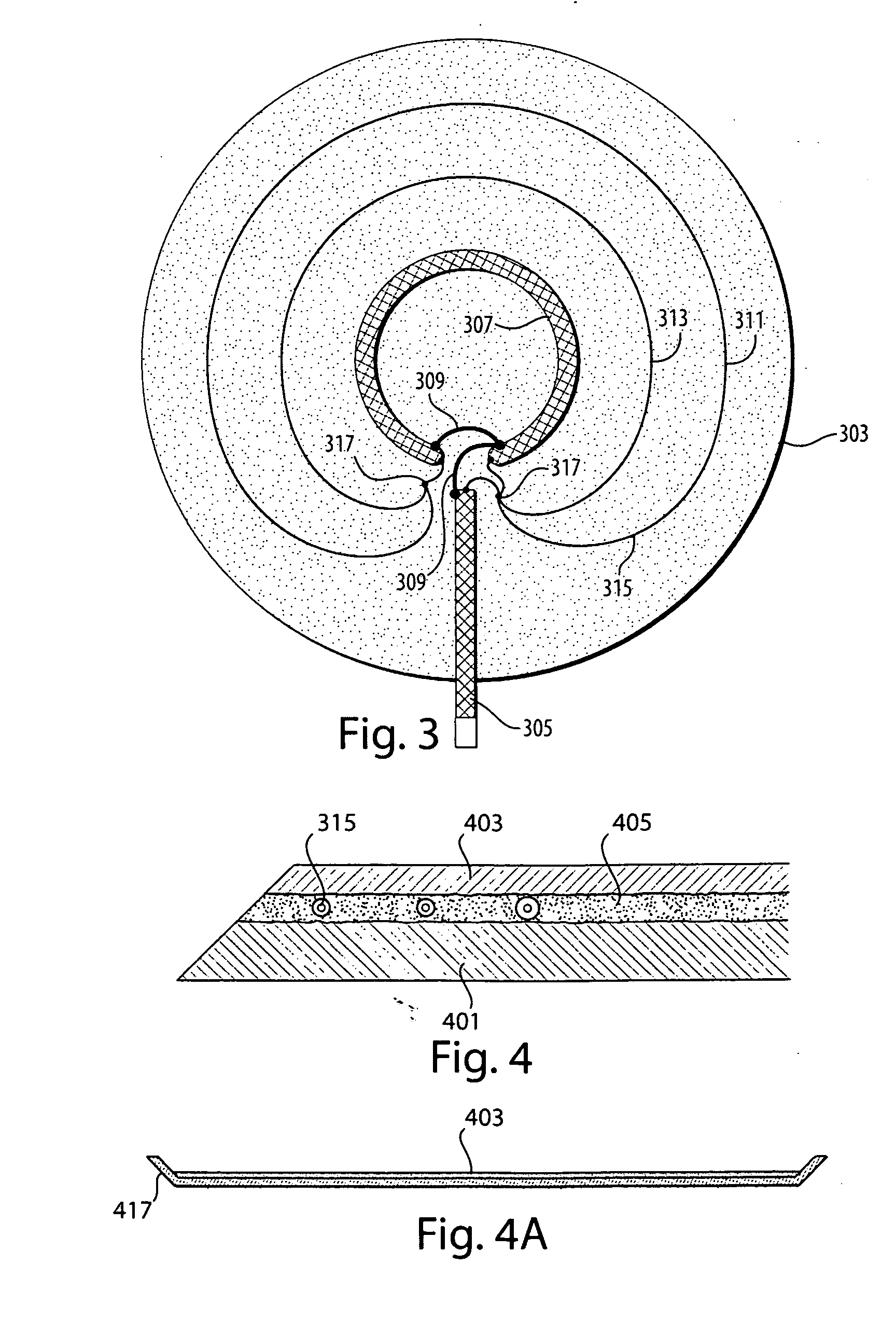
[0010]The invention is a generally flat, flexible magnetic loop type antenna optimized for placement close to or adjacent to a floor, such as a stage floor, or under a carpet, such as found in a church, and having a plurality of loops embedded inside, a robust matching section, and an output consisting of at least one signal line such as a coaxial or other cable that can be further routed to a receiver, a transmitter, a transceiver, or a reradiation system. The flat antenna may be embedded in a polymer that is durable and water tight using a layered process. The invention also consists of the method of using a proximate floor mounted antenna system to selectively receive and or transmit the low powered radiofrequency or “RF” signals to and from wireless devices such as wireless body packs, instrument transmitters, pickups, microphones and the like.

Problems solved by technology

The use of radio spectrum for such local use is frequently hampered by the presence of external RF generators such as radio broadcasting, television, two-way radio systems and other systems such as paging systems and cellular telephony systems.
Exacerbating the problem is the frequent requirement for more than one channel of information to be transmitted at a given time.
In other instances, a combination of transmitters comprising one-way and two-way devices may interfere with one each other, and with distant yet powerful external RF generators.
These distant RF generators may also interfere with the local use of relatively lower powered devices such as bodypacks, and battery powered wireless devices such as instrument pickups, microphones, transducers, data generators, and the like.
Crowded RF spectrum space makes it increasingly difficult for prior art low powered local RF transmission systems to reliably operate in without interference, noise and signal degradation.
Continued use of conventional long distance antenna systems for in building use has exacerbated the problem by picking up even more externally generated interference.
Cost and performance limited receivers used in these applications have limited dynamic range and rely on analog transmission of frequency modulated signals to achieve near zero latency, which is a requirement for music, and desirable for voice applications.
Frequency modulation (FM) is known for the so-called capture effect, which reduces interference, however FM capture effect is not effective in current art wireless body pack and microphone systems because carrier frequencies are not “zero beat” or precise enough to eliminate heterodyne beat note interference, even within same product families.
Transmitters commonly used in so-called body packs and other devices such as wireless microphones and pickups typically employ channelized operation allowing users to select specific clear frequencies, either manually or automatically, but source oscillators are not precise, and synthesizers used to generate multiple frequencies may be noisy and produce inter-system interference and beat notes even without interference from external television, white space devices, or other unpredictable or uncontrollable sources of interfering radiofrequency interference.

Method used


Image

  • Wireless conformal antenna system and method of operation
  • Wireless conformal antenna system and method of operation
  • Wireless conformal antenna system and method of operation

Examples


Embodiment Construction

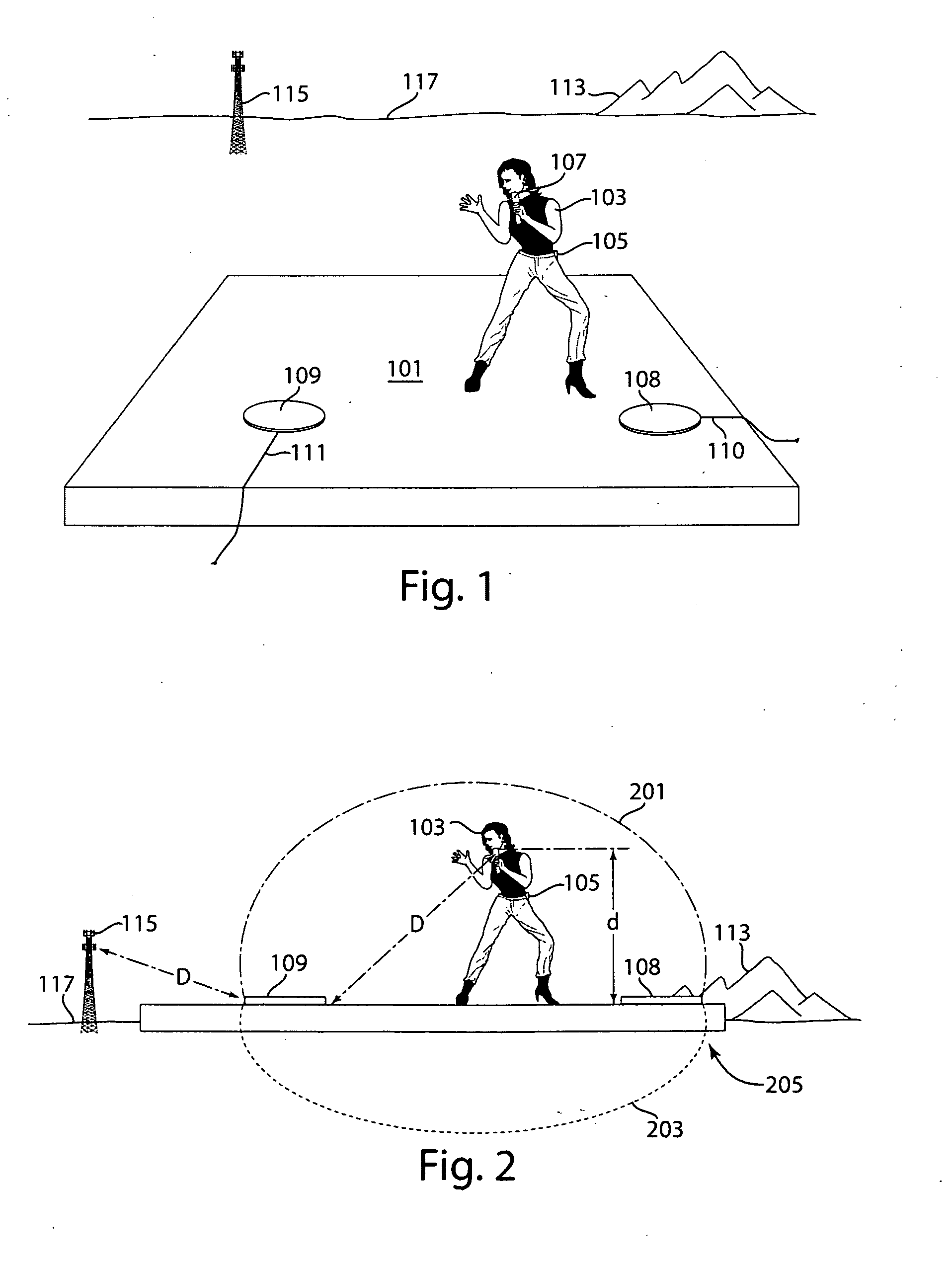
[0025]Referring now to FIG. 1, the a perspective view of a typical stage arrangement with a performer thereupon, using a wireless device, and a plurality of floor positioned antenna pads, stage 101 may be comprised of various materials that are important to the operation of the invention, such as metal, wood, concrete or carpet, or earth. Performer 103 may wear wireless bodypack 105, which is a low power battery operated transmitter that can be concealed and connected to a musical instrument such as an electric guitar (not shown). Performer 103 may also use a wireless microphone 107, which is comprised of a battery powered transmitter connected to an air coupled transducer capable of picking up vocal or music sounds and generating a modulated low power radio signal. A first floor-antenna 108 is preferably positioned flat upon the stage 101 or as part of the stage, as an unrolled rug, mat and / or part of the set, which may also require some contouring, in such a way as to be out of si...


PUM

PropertyMeasurementUnit
Thicknessaaaaaaaaaa
Sensitivityaaaaaaaaaa
Frequencyaaaaaaaaaa

Abstract

A conformal antenna system comprising one or more proximate antenna elements for very reliable localized reception and transmission of radiowave energy and power particularly in frequency controlled VHF, UHF and microwave spectrum is described. The system incorporates effective angle or proximity dependent interference mitigation for conventional transmitters / receivers or master controlled constellations of wireless devices, and is suitable for temporary or permanent installation and use in a variety of outdoor and in-building locations. The antenna elements are configured and optimized for close proximity but unobtrusive positioning near the point of use on stages, in concert halls, movie studios, houses-of-worship, and convention centers, and are configured to be relatively unaffected by people or furniture in very close proximity. Methods for manufacturing and using close proximity antennas are disclosed, as are systems and methods for the generation and control of signals thereto.

Description

BACKGROUND OF THE INVENTION[0001]1. Field of the Invention[0002]The present invention relates to antennae, and more particularly to low profile readily configurable antennae which is based upon Provisional Patent application No. 61 / 341,941, filed 7 Apr. 2010, and which is incorporated herein by reference in its entirety.[0003]2. Discussion of Prior Art[0004]Localized antennas and radio transmission systems are well known in the art and typically comprise a signal source, a modulator, an RF generating transmitter, and a radiating antenna used in conjunction with a receiver that incorporates at least one antenna, an RF front end, a receiver and demodulation system, and an output system. The output system may comprise demodulated data, audio, video or other signals such as telemetry. Such systems are often used on stages, in churches, and other performance spaces and venues.[0005]The use of radio spectrum for such local use is frequently hampered by the presence of external RF generato...

Claims


Application Information

Patent Timeline
IPC IPC(8): H04B7/08H01P11/00H01Q21/00H04B7/06H04B3/00
CPCH01Q1/40Y10T29/49018H01Q7/00
Inventor CROWLEY, ROBERT J.
Owner RF VENUE
Learn More